Eureka AIR delivers breakthrough ideas for toughest innovation challenges, trusted by R&D personnel around the world.

Protective layer structure of plasma display panel (PDP) front glass plate and preparation method thereof

A technology of front glass plate and protective layer, which is applied in the field of protective layer structure of Plasma Display (PDP), can solve the problems of image quality degradation, opaque film, and lack of protective effect, so as to reduce ignition voltage and addressing time, the effect of reducing power consumption

Inactive Publication Date: 2013-04-24
UNIV OF ELECTRONIC SCI & TECH OF CHINA +1
View PDF14 Cites 1 Cited by
  • Summary
  • Abstract
  • Description
  • Claims
  • Application Information

AI Technical Summary

Problems solved by technology

But the biggest disadvantage of this structure is due to the LaB 6 The film is opaque, if it is to completely cover the transparent medium layer, it will affect the photoelectric conversion efficiency of the PDP and cause the image quality to decline; if it is made into a dispersed island structure, on the one hand, it cannot fully cover the transparent medium layer and thus cannot protect it. It is necessary to change the existing drive mode, which is not compatible with the existing production process

Method used


Image

  • Protective layer structure of plasma display panel (PDP) front glass plate and preparation method thereof
  • Protective layer structure of plasma display panel (PDP) front glass plate and preparation method thereof
  • Protective layer structure of plasma display panel (PDP) front glass plate and preparation method thereof

Examples


Embodiment Construction

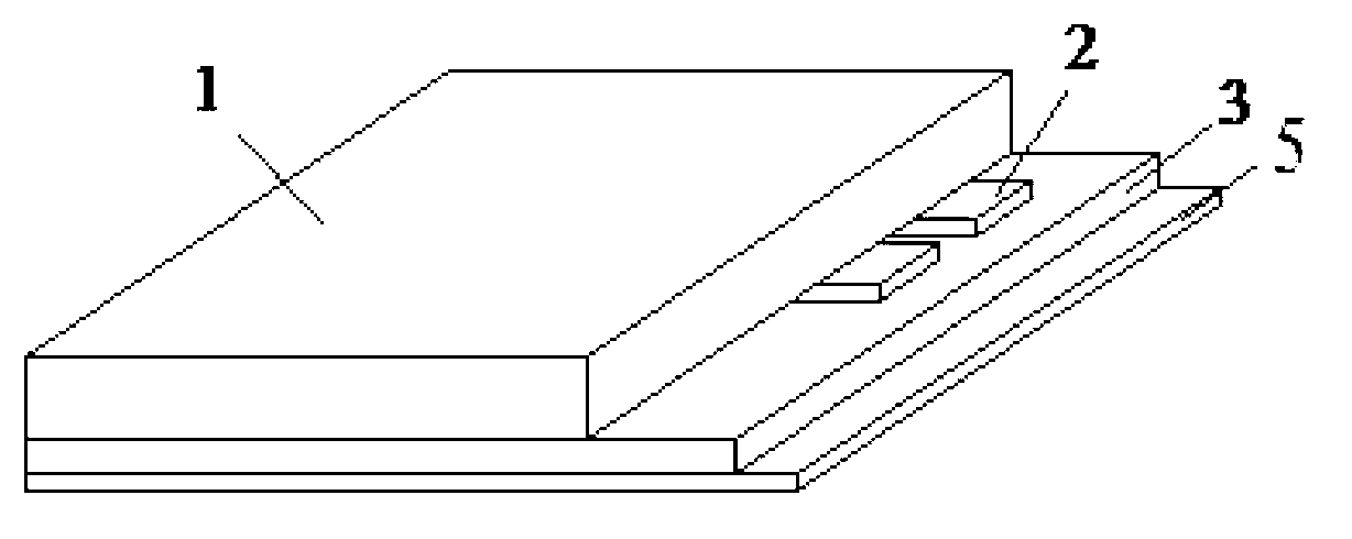
[0022] Such as figure 2 As shown, a protective layer structure of the PDP front glass plate is located on the surface of the transparent medium 3 of the PDP front glass plate, and there is a scanning and sustaining transparent electrode 2 between the transparent medium 3 and the glass substrate 1 . The protective layer structure 5 is a small amount of LaB doped 6 MgO material, where LaB 6 The incorporation amount of the PDP is limited not to significantly reduce the light transmittance of the PDP front glass plate (the decrease rate of the light transmittance of the PDP front glass plate is limited to no more than 5%~10%).

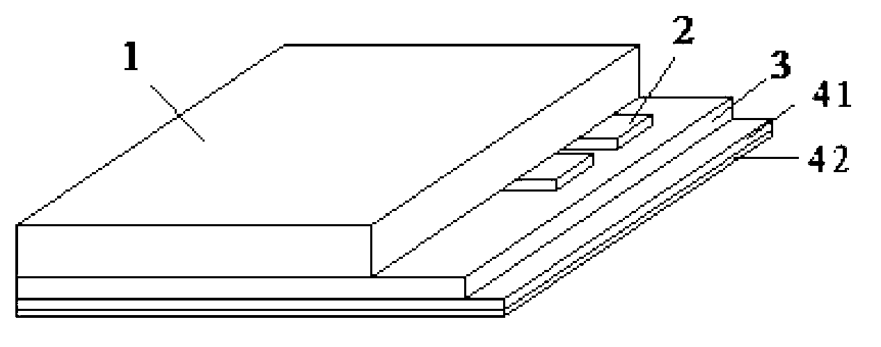
[0023] Such as image 3 As shown, a protective layer structure of the PDP front glass plate is located on the surface of the transparent medium 3 of the PDP front glass plate, and there is a scanning and sustaining transparent electrode 2 between the transparent medium 3 and the glass substrate 1 . The protective layer structure includes a MgO protecti...


PUM


Abstract

The invention provides a protective layer structure of a plasma display panel (PDP) front glass plate, and belongs to the technical field of photoelectric materials and devices. The protective layer structure is arranged on the surface of transparent medium (3) of the PDP front glass plate, and is a composite protective layer structure which is formed by magnesium oxide (MgO) materials or an MgO protective layer mixed with a small amount of lanthanum hexaboride (LaB6) and discontinuous LaB6 thin film arranged on the surface of the MgO protective layer. The protective layer structure can be achieved by using a screen printing technology or a spraying technology. Due to the fact that the LaB6 which has a low work function characteristic is added on the basis of indistinctively reducing light transmittance of the front glass plate, a PDP displayer is enabled to be capable of reducing firing voltage and addressing time, and total consumption of the PDP displayer is reduced.

Description

technical field [0001] The invention belongs to the technical field of photoelectric materials and devices, in particular to a protective layer structure of a plasma display (PDP). Background technique [0002] Since the color plasma display (PDP) was introduced to the market in the 1990s, the development has become more and more mature. The working principle of the PDP is to apply a strong electric field to both ends of the low-pressure inert gas, causing its breakdown to generate strong ionization to directly emit light or generate ultraviolet light to excite the phosphor to emit light. Because of its active light emission, no need for backlight, fast response, small thickness, light weight, large display area, no display viewing angle problem, bright image color and working in full digital mode, it has been widely concerned and applied by the world's electronics industry. [0003] The luminous efficiency of PDP can be expressed by the following formula: η=η dis ·η uv ·...

Claims


Application Information

Patent Timeline
IPC IPC(8): H01J11/40H01J9/24
Inventor 王小菊林祖伦祁康成曹贵川邓江尹伊
Owner UNIV OF ELECTRONIC SCI & TECH OF CHINA
Why Eureka
Eureka Blog
Learn More