Conduction-variable vacuum water catching device

A vacuum and water trap technology, which is used in steam condensation, chemical instruments and methods, separation methods, etc., can solve the problems of low water vapor trapping efficiency, low density, and large water consumption, so as to improve the trapping efficiency and heat conduction. Good performance and improved efficiency

Active Publication Date: 2013-05-01
LIAOYANG BOSHI FLUID EQUIP
View PDF5 Cites 4 Cited by
  • Summary
  • Abstract
  • Description
  • Claims
  • Application Information

AI Technical Summary

Problems solved by technology

In these industrial fields, the vacuum water catch system (water catcher) used before has many shortcomings, which are mainly reflected in: ① When the water catcher is running without load, the gas conduction capacity is unchanged. After work, due to The wall of the condensation pipe at the inlet of the water trap first contacts the water vapor and forms ice or frost, which occupies the space for the pumped gas to pass through and affects the passage of the pumped gas, causing the condensation pipe at the back of the water trap to fail to collect. No or little water vapor is captured, resulting in low efficiency of capturing water vapor, wasting energy, making the structure of the water trap huge, wasting metal materials, and occupying a large area; Frost, frosting and icing have different effects. Frost has a low density and poor thermal conductivity, which affects the capture of water vapor. Ice has a high density and good thermal conductivity. In the case of the same capture area, it can More water vapor is captured, which improves the collection efficiency of the water catcher; ③ The defrosting methods mainly include water flooding and spraying. The watering method consumes a lot of water, defrosting is slow, and takes a long time; There are two types, hot water spray and steam spray, both methods require a heat source, resulting in energy waste

Method used


Image

  • Conduction-variable vacuum water catching device
  • Conduction-variable vacuum water catching device
  • Conduction-variable vacuum water catching device

Examples


Embodiment 1

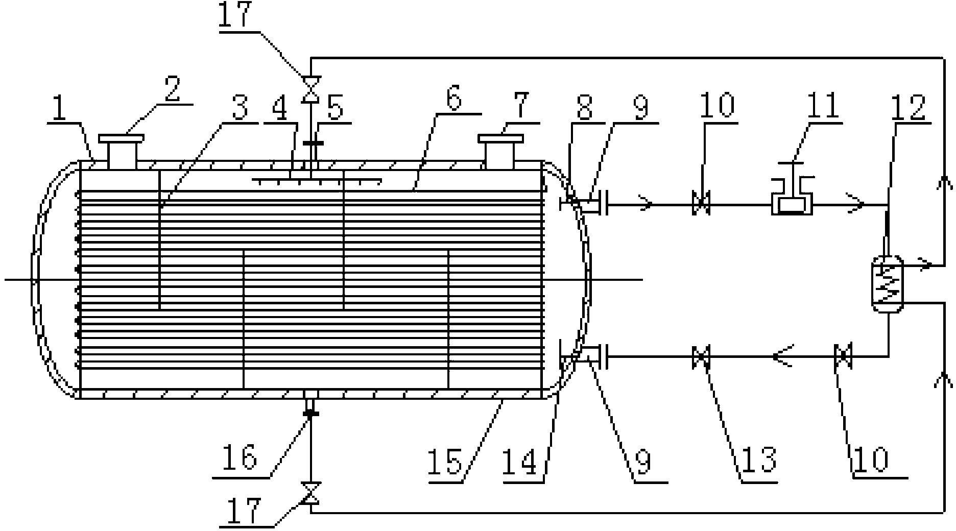
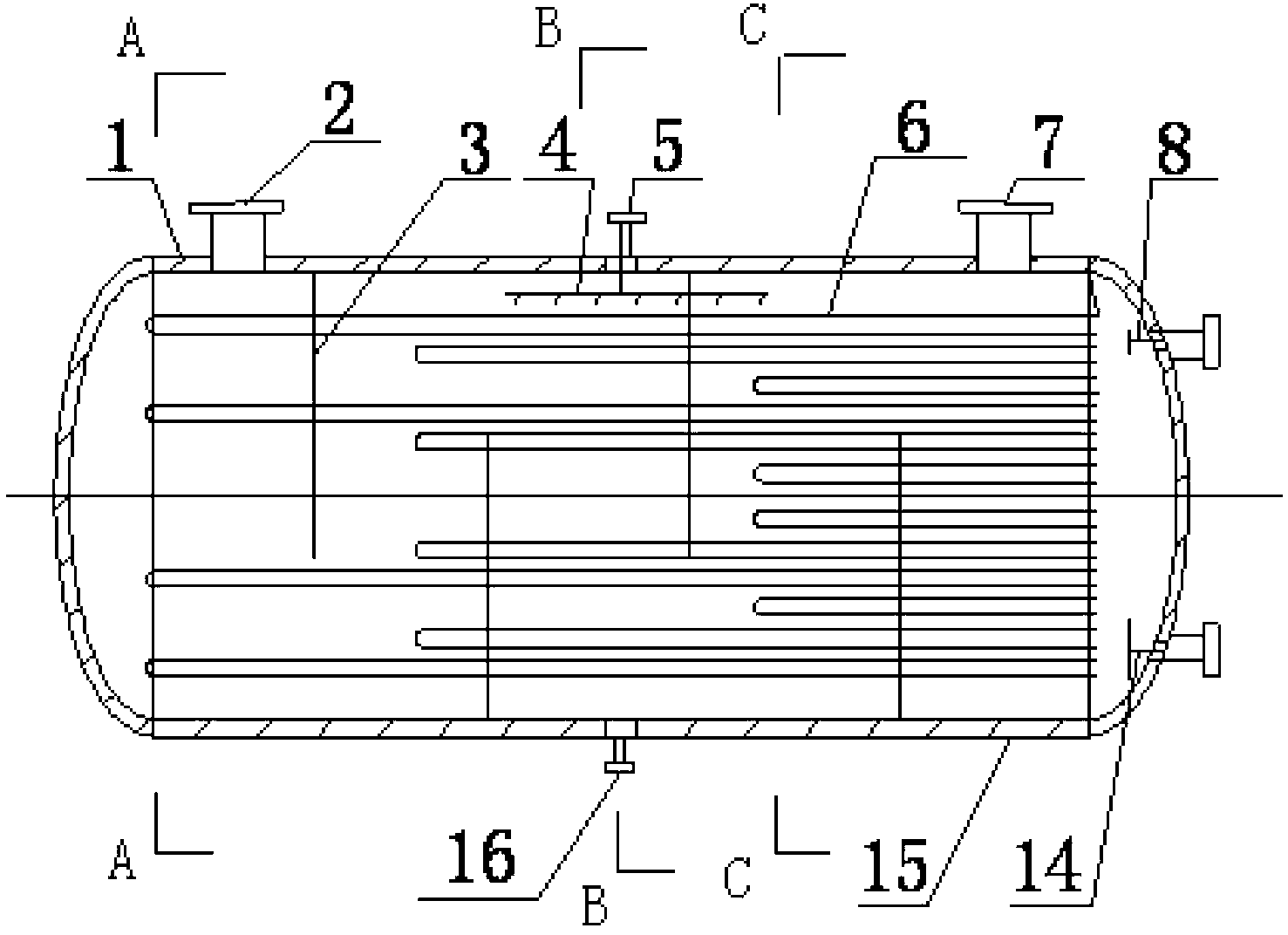
[0023] Such as figure 2 As shown, the water trap structure of an embodiment of the present invention includes a housing 1, an air inlet 2, a fan-shaped baffle 3, a spray pipe 4, a water inlet 5, a condenser pipe 6, an exhaust port 7, and a collecting pipe 8. Diversion pipe 14, insulation layer 15, drainage port 16. A water inlet 5 is provided on the upper surface of the housing, an air inlet 2 is provided on one side of the water inlet 5, and an air outlet 7 is provided on the other side. A spray pipe 4 is provided between the water inlet 5 and the condenser pipe 6. A drain port 16 is provided below the casing. A header 8 is provided at the upper end of one side of the housing, and a shunt tube 14 is provided at the lower end. An insulation layer 15 is provided on the outer layer of the shell. The air inlet 2 is connected to the pumped container (the working container that needs to extract water vapor) through a valve, and the air outlet 7 is connected to the vacuum pump th...

Embodiment 2

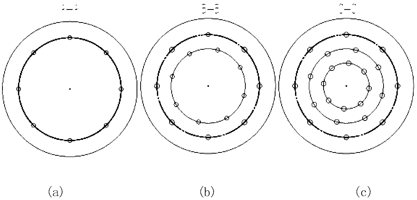
[0025] Such as Figure 4 As shown, the water trap structure of another embodiment of the present invention includes a housing 1, an air inlet 2, a spray pipe 4, a water inlet 5, a condenser pipe 6, an exhaust port 7, a collecting pipe 8, and a branch pipe 14. , Insulation layer 15, drainage outlet 16, circular baffle 18, circular baffle 19. A water inlet 5 is provided on the housing, an air inlet 2 is provided on one side of the water inlet 5, and an air outlet 7 is provided on the other side. A spray pipe is arranged between the water inlet 5 and the condenser pipe 6. A drain port 16 is provided below the casing. A collecting pipe 8 is provided at the upper end of one side of the housing, and a shunt pipe 14 is provided at the lower end. An insulation layer 15 is provided on the outer layer of the shell. The air inlet 2 is connected to the pumped container (the working container that needs to extract water vapor) through a valve, and the air outlet 7 is connected to the vac...


PUM


Abstract

The invention discloses a conduction-variable vacuum water catching device and belongs to the technical field of vacuum water catching. The vacuum water catching device comprises a water catcher, a refrigerating system and an auxiliary unit; a condenser tube shortens gradually in length in the direction from the gas inlet to the gas outlet, so that the conduction capacity of the water catcher varies from large to small when gas flows in the water catcher; a casing adopts a modified taper, and circular and round baffle plates are adopted for the inside of the taper casing, therefore the conduction capacity of the water catcher also varies from large to small when the gas flows in the water catcher, moreover, the efficiency for catching steam is improved, and the refrigerating capacity consumption is reduced. As the device adopts cooling water circulation for defrosting or deicing, reuse of waste water as well as heat energy is achieved, and purposes of high efficiency, energy saving and emission reduction are achieved; the device is simple in structure, low in construction cost, convenience in use and maintenance, and large in application range, and can be used wherever the steam is required to be caught.

Description

Technical field [0001] The invention belongs to the technical field of vacuum water capture, and particularly relates to a variable conduction vacuum water capture device. Background technique [0002] In modern industry, there are many industrial fields that need to extract water vapor. For example: vacuum distillation can be used in vacuum metallurgy, petrochemical industry, seawater desalination, edible oil deodorization, decolorization, etc.; vacuum drying can be used in food processing, pharmaceutical production, new material development, etc.; vacuum pressure impregnation can be used in motors, transformers, capacitors The dipping paint and so on. In these industrial fields, the vacuum water trapping system (water trap) used before has many shortcomings, which are mainly reflected in: ①When the water trap is running at no load, the conduction capacity of the gas is unchanged. The condensing tube wall at the entrance of the water trap first comes into contact with water va...

Claims


Application Information

Patent Timeline
Patent Type & Authority Applications(China)
IPC IPC(8): B01D5/00
Inventor 王德喜谢元华刘波范丽华
Owner LIAOYANG BOSHI FLUID EQUIP
Why Eureka
Try Eureka