
Low-temperature air intake method for internal combustion engine and engine

A technology for an engine and an internal combustion engine, which is applied to the low-temperature air intake method of an internal combustion engine and the field of the engine, can solve the problems of consuming other work or low-temperature substances, increasing the intake air volume, reducing the thermal efficiency, etc., and achieving energy saving and environmental protection, high utilization rate, structure simple effect

Active Publication Date: 2013-05-01
菏泽天利纺织有限公司
View PDF9 Cites 11 Cited by
  • Summary
  • Abstract
  • Description
  • Claims
  • Application Information

AI Technical Summary

Problems solved by technology

However, since the degree of fuel combustion in the cylinder is related to the intake air volume, it will burn more fully when the intake air is excessive, thereby generating more heat; while reducing the intake air temperature while the cylinder volume remains unchanged, the intake air will increase correspondingly. quantity
Therefore, in reducing the intake air temperature, people have developed a series of devices to achieve this purpose, such as adding coolers or other heat-absorbing devices to the intake passage. Although it can reduce the intake air temperature, it needs to consume other work or low-temperature substances. Increases the cost of manufacturing the engine or reduces its efficiency
In addition, the exhaust gas of the engine contains a large amount of heat energy and has not been effectively utilized, but it is directly discharged, which also reduces the thermal efficiency accordingly.

Method used


Image

  • Low-temperature air intake method for internal combustion engine and engine
  • Low-temperature air intake method for internal combustion engine and engine
  • Low-temperature air intake method for internal combustion engine and engine

Examples


Embodiment 1

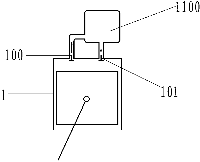
[0058] Such as figure 1 The residual energy refrigeration low-temperature engine shown includes a cylinder-piston mechanism 1, and the exhaust passage of the cylinder-piston mechanism 1 is provided with a refrigeration unit 1100 driven by exhaust energy, and the refrigeration unit 1100 is used to cool the Intake air in the intake duct of the cylinder-piston mechanism 1.

Embodiment 2

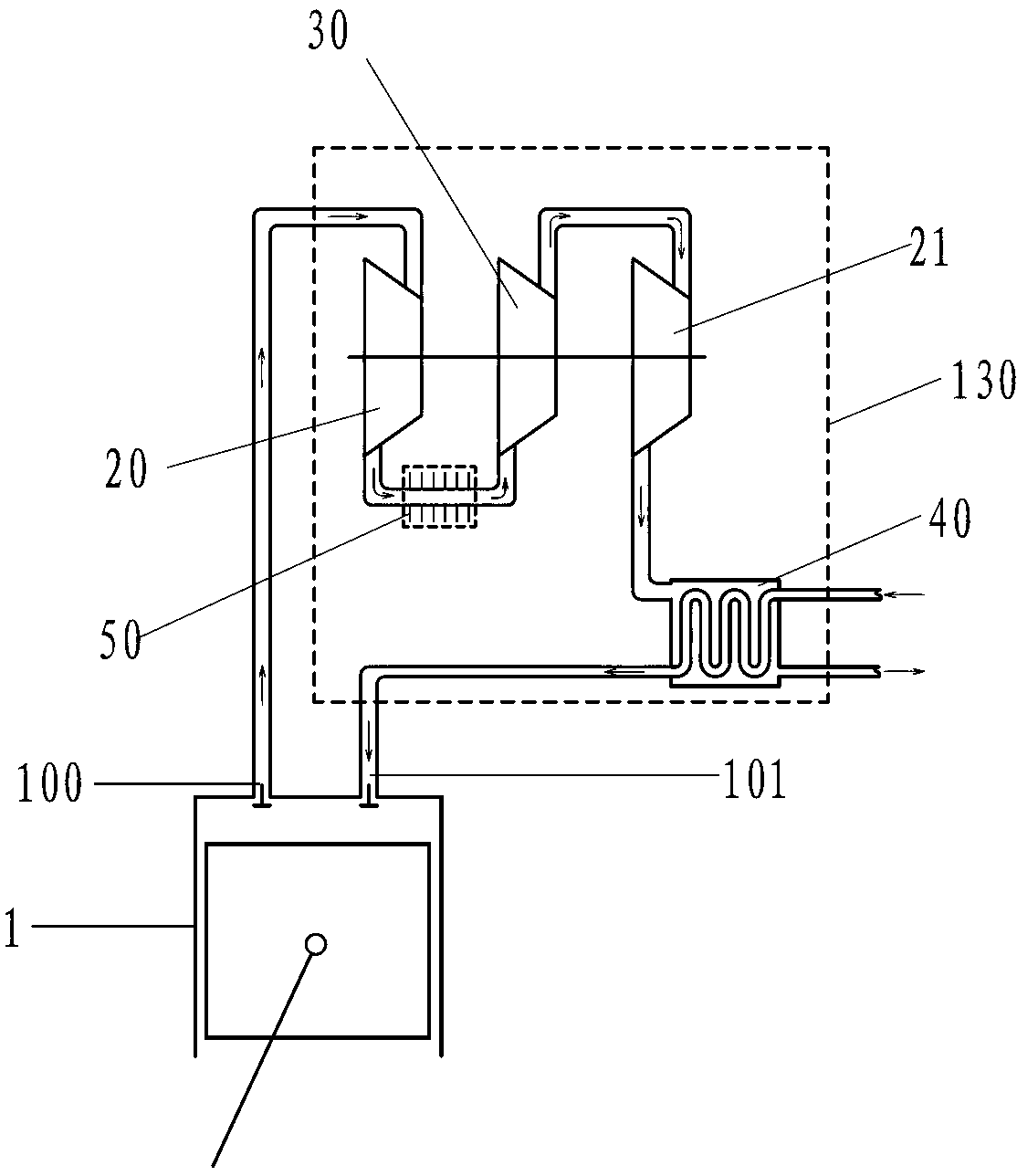
[0060] Such as figure 2 The difference between the residual energy refrigeration low-temperature engine shown in Embodiment 1 is that the refrigeration unit 1100 is a compression expansion refrigeration unit A 130 ( figure 2 The dotted box shown in ), the compression expansion refrigeration unit A 130 includes a turbine power mechanism A 20 , an impeller compressor A 30 , a turbine power mechanism B 21 and a heat exchanger A 40 connected in sequence; A cooler A 50 is provided on the communication passage between A 20 and impeller compressor A 30, and the turbine power mechanism A 20 and the impeller compressor A 30 are coaxially arranged; the exhaust passage of the cylinder-piston mechanism 1 is connected to The working fluid inlet of the turbine power mechanism A 20 is connected, and the working fluid outlet of the turbine power mechanism B 21 is connected with the heated fluid inlet of the heat exchanger A 40; the cooled fluid of the heat exchanger A 40 The outlet communi...

Embodiment 3

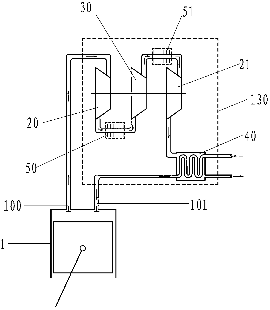
[0063] Such as image 3 The difference between the residual energy cooling low-temperature engine shown in Embodiment 2 is that a desuperheater B 51 is provided on the communication channel between the impeller compressor A 30 and the turbine power mechanism B 21 .


PUM


Abstract

The invention discloses a low-temperature air intake method for an internal combustion engine, and an engine. The engine comprises an air cylinder piston mechanism, wherein an exhaust channel of the air cylinder piston mechanism is provided with a refrigerating unit in which exhaust residual energy is taken as driving force; and the refrigerating unit is used for cooling inflow air in an air intake channel of the air cylinder piston mechanism. According to the residual energy refrigeration low-temperature engine provided by the invention, the residual energy of exhaust is used for acting, so that the air intake temperature of the air cylinder piston mechanism is lowered, and the efficiency of the engine is increased.

Description

technical field [0001] The invention relates to the field of thermal energy and power, in particular to a low-temperature air intake method for an internal combustion engine and the engine. Background technique [0002] Thermodynamic cold source temperature T 2 The reduction of will significantly improve the efficiency of the heat engine. Internal combustion engine is a kind of heat engine, but for internal combustion engine, the thermodynamic cold source temperature T 2 Whether it is the intake air temperature, the ambient temperature or the temperature of the working medium at the end of the power stroke, there are many opinions on this, but the inventor believes that for internal combustion engines, the thermodynamic heat sink temperature T 2 Neither the intake air temperature, nor the ambient temperature, nor the temperature of the working fluid at the end of the power stroke, but the combination of the temperature of the working fluid at the beginning of the compressi...

Claims


Application Information

Patent Timeline
Patent Type & Authority Applications(China)
IPC IPC(8): F01N5/04F02B29/04
CPCY02T10/146Y02T10/16Y02T10/12
Inventor 靳北彪
Owner 菏泽天利纺织有限公司
Learn More