
Control method of oil temperature of compressor

A control method and compressor technology, applied in pump control, mechanical equipment, machine/engine, etc., can solve problems such as slow heating, wear and tear, and long time

Active Publication Date: 2013-05-01
NINGBO AUX ELECTRIC
View PDF6 Cites 12 Cited by
  • Summary
  • Abstract
  • Description
  • Claims
  • Application Information

AI Technical Summary

Problems solved by technology

[0002] As we all know, during the operation of the compressor, especially during the operation of low-temperature heating conditions, the oil temperature is too low, which will cause the refrigerant to easily condense in the compressor, dilute the oil film and reduce the viscosity of the lubricating oil, resulting in poor lubrication between the parts of the compressor However, serious wear and tear will damage the compressor. In order to solve the above problems, the current control method of compressor oil temperature is mainly to preheat the compressor by controlling the oil temperature and electric heating belt, so as to ensure its normal start-up under low temperature conditions, but this method There are the following defects, 1. The working principle of the oil temperature electric heating belt is to preheat the lubricating oil of the compressor. The heating is slow, and it takes a long time for the preheating to reach a certain temperature, which obviously prolongs the waiting time for starting up. 2. The oil temperature electric heating belt needs to consume electric energy. 3. The oil temperature electric heating belt is limited to ensure that the compressor starts up well, and the compressor cannot guarantee a good oil temperature range when it is running at low temperature

Method used


Image

  • Control method of oil temperature of compressor

Examples


Embodiment Construction

[0010] The present invention will be further described below in conjunction with accompanying drawing.

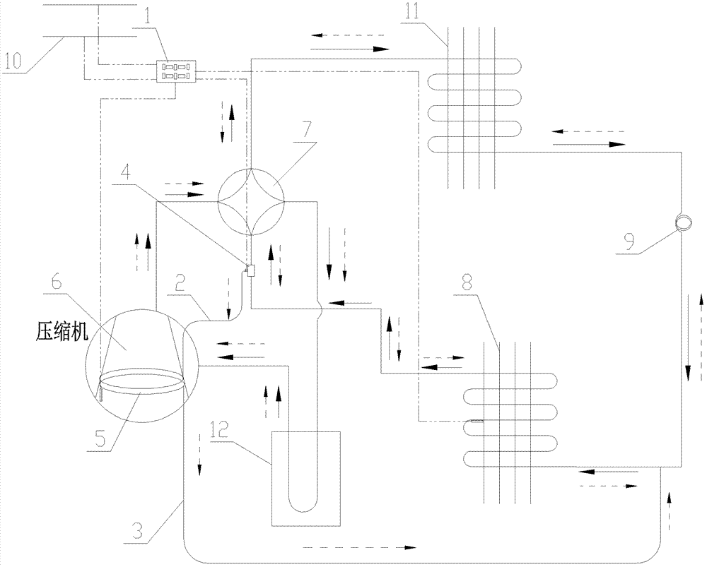
[0011] In the method for controlling the oil temperature of the compressor in the present invention, when the compressor 6 is started or running, if the ΔT-prescribed value<0, then the high-temperature refrigerant in the pipeline used to transport the high-temperature refrigerant during the heating of the air conditioner is led to the compressor. machine 6 to heat the bottom surface of the compressor 6 shell, in actual use, only a small part of the high-temperature refrigerant is drained to heat the compressor 6 shell; during the process of heating the compressor 6 shell by the high-temperature refrigerant, if ΔT- If the specified value is greater than or equal to 0 and lasts for 3 minutes, then disconnect the high-temperature refrigerant leading to the compressor 6, that is, stop using the high-temperature refrigerant to heat the bottom of the compressor 6 shell, otherwise ...


PUM


Abstract

The invention discloses a control method of oil temperature of a compressor, which has the advantages of no waiting time for starting and energy saving, and a good oil temperature range can be guaranteed when the compressor is operated at low temperature. During starting or operation of the compressor, if the difference between delta T and a specified value is less than 0, a high-temperature refrigerant in a pipeline which is used for conveying the high-temperature refrigerant when an air conditioner is operated in a heating mode is led to the compressor, so as to heat the bottom of a housing of the compressor; in the process that the bottom of the housing of the compressor is heated by the high-temperature refrigerant, if the difference between the delta T and the specified value is greater than or equal to 0 and continues for at least two minutes, the high-temperature refrigerant which is led to the compressor is disconnected, and otherwise, the high-temperature refrigerant continues heating the bottom of the housing of the compressor; and the delta T is the difference between the lubricating oil temperature of the compressor and the steam temperature or the difference between the temperature of the bottom of the housing of the compressor and the saturation temperature corresponding to the discharge pressure, and the specified value is a minimum value which is required in a functional specification of the compressor and is at least equal to or greater than the difference between the temperature of the bottom of the housing of the compressor 6 and the saturation temperature corresponding to the discharge pressure.

Description

technical field [0001] The invention relates to the technical field of air conditioning, in particular to a method for controlling oil temperature of a compressor. Background technique [0002] As we all know, during the operation of the compressor, especially during the operation of low-temperature heating conditions, the oil temperature is too low, which will cause the refrigerant to easily condense in the compressor, dilute the oil film and reduce the viscosity of the lubricating oil, resulting in poor lubrication between the parts of the compressor However, serious wear and tear will damage the compressor. In order to solve the above problems, the current control method of compressor oil temperature is mainly to preheat the compressor by controlling the oil temperature and electric heating belt, so as to ensure its normal start-up under low temperature conditions, but this method There are the following defects, 1. The working principle of the oil temperature electric he...

Claims


Application Information

Patent Timeline
Patent Type & Authority Applications(China)
IPC IPC(8): F04B39/06F04B49/06
Inventor 郑坚江熊景华贾毛伟
Owner NINGBO AUX ELECTRIC
Learn More