

Continuous feeding device for electric arc furnace preheated by flue gases
A technology of feeding device and electric arc furnace, which is applied in the field of metallurgical equipment, can solve problems such as inaccessibility to engineering, complexity of pipeline system, difficulty in installation and maintenance, etc., and achieve longer residence time of flue gas, improved preheating effect, and mechanical high efficiency effect
- Summary
- Abstract
- Description
- Claims
- Application Information
AI Technical Summary
Problems solved by technology
Method used
Image

Examples
Embodiment Construction
[0020] The present invention will be further described below in conjunction with the accompanying drawings and embodiments.
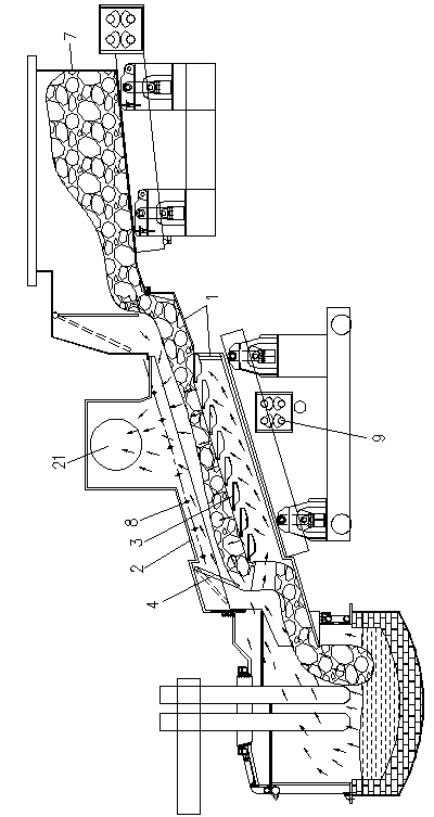
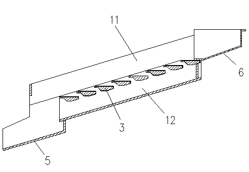
[0021] As shown in the figure, this embodiment utilizes the electric arc furnace continuous feeding device for flue gas preheating, including a double-duct feeding chute 1 and a smoke guide hood 2, and the double-duct feeding trough 1 is high at the feed end and the outlet is high. The material end is low and inclined, and the middle part of the double-duct trough 1 is provided with a material carrier plate 3 with a flue gas channel. The upper part of the material carrier plate 3 is a material flow channel 11, and the lower part of the material carrier plate is a flue gas circulation. Duct 12, the upper part of the material circulation duct 11 is an opening, the high end of the smoke circulation duct 12 is closed, and the smoke guide hood 2 is provided with a seal that cooperates with the upper opening of the lower end of the material circulation duct 11...
PUM
 Abstract
Description
Claims
Application Information