
Method and device for generating temperature lookup table of optical module

A look-up table and optical module technology, applied in the field of optical communication, can solve the problems of long time required, low temperature look-up table efficiency, and many production resources, etc.

Active Publication Date: 2013-05-01
HISENSE BROADBAND MULTIMEDIA TECH
View PDF5 Cites 38 Cited by
  • Summary
  • Abstract
  • Description
  • Claims
  • Application Information

AI Technical Summary

Problems solved by technology

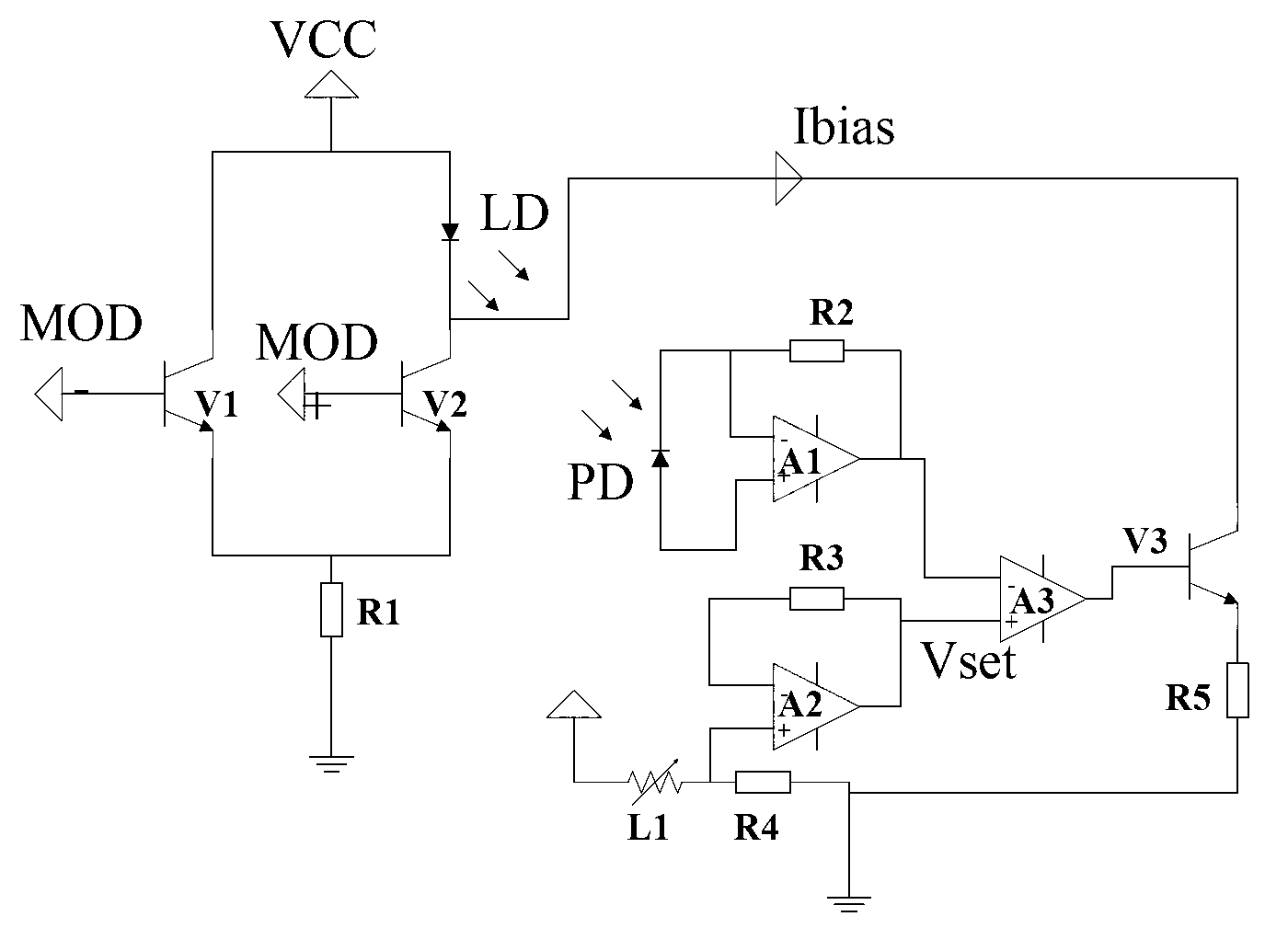
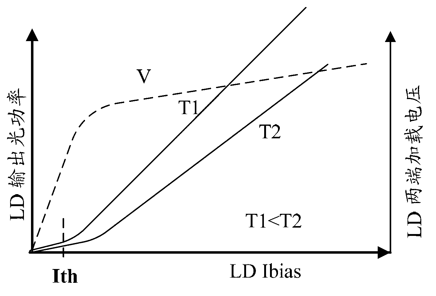
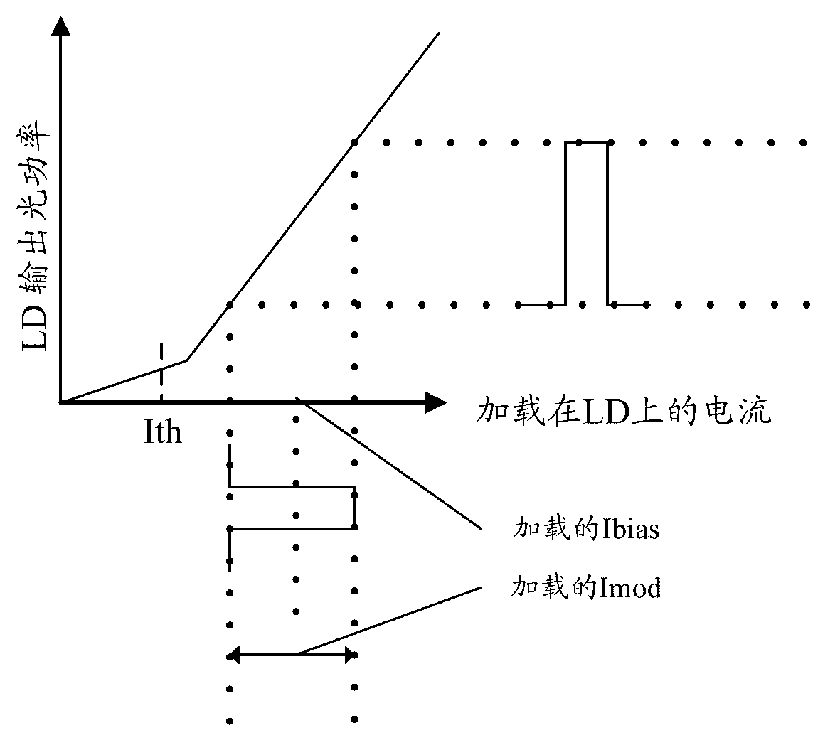
[0011] It can be seen from the above that the existing method for generating the temperature lookup table of the optical module needs to test each optical module within the working temperature range to determine the modulation current and the bias current setting value corresponding to the correction point in the follow-up work, Usually, high and low temperature boxes or air guns are used to adjust the temperature of the optical module to various operating temperature points, and it takes time to stabilize the temperature of the optical module from rising / cooling. Therefore, this routine generates the optical module temperature lookup table The method needs to be specific to each optical module, which requires a long time, low efficiency in generating the optical module temperature lookup table, and takes up a lot of production resources, which is not conducive to the improvement of the production efficiency of the production line.

Method used


Image

  • Method and device for generating temperature lookup table of optical module
  • Method and device for generating temperature lookup table of optical module
  • Method and device for generating temperature lookup table of optical module

Examples


Embodiment Construction

[0123] In order to make the object, technical solution and advantages of the present invention clearer, the present invention will be described in further detail below with reference to the accompanying drawings and preferred embodiments. However, it should be noted that many of the details listed in the specification are only for readers to have a thorough understanding of one or more aspects of the present invention, and these aspects of the present invention can be implemented even without these specific details.

[0124] As used herein, terms such as "module" and "system" are intended to include computer-related entities such as, but not limited to, hardware, firmware, a combination of hardware and software, software, or software in execution. For example, a module may be, but is not limited to being limited to being, a process running on a processor, a processor, an object, an executable, a thread of execution, a program, and / or a computer. For example, both an applicatio...


PUM


Abstract

The invention discloses a method and a device for generating a temperature lookup table of an optical module. The method comprises the following steps of: adjusting light power output by a tested optical module and an extinction ratio to preset target values, and acquiring the testing temperature value, testing offset current set register value and testing modulation current set register value of the optical module on a temperature point; normalizing the acquired current value, and acquiring the current normalization slope coefficient parameter of a temperature interval formed by each temperature point; adjusting light power output by an optical module to be applied and the extinction ratio to preset target values, and acquiring the working temperature value, offset current set register value and modulation current set register value of the optical module in a normal-temperature environment; and normalizing a slope coefficient parameter in combination with pre-acquired current to generate a current temperature lookup table of the optical module to be applied, and writing the generated current temperature lookup table into the optical module to be applied. Due to the application of the method and the device, the generating efficiency of the temperature lookup table of the optical module can be increased.

Description

technical field [0001] The invention relates to optical communication technology, in particular to a method and device for generating an optical module temperature lookup table. Background technique [0002] In the current domestic market and international market, the direction of optical fiber communication with high bandwidth, high speed and multi-service integration has begun to be applied; among many solutions, the emergence of fiber-to-the-home (FTTH, FiberTo The Home) is considered to be the key to broadband access. The ultimate solution for the entry, the domestic market has been widely used. [0003] The optical module is the core component of FTTH in the optical fiber communication system. The stability of the overall performance of the optical module is directly related to the performance stability of the optical fiber communication system. The performance of the optical port at the transmitting end of the optical module, that is, the quality of the transmitted opt...

Claims


Application Information

Patent Timeline
Patent Type & Authority Applications(China)
IPC IPC(8): H01S5/068H01S5/0683
Inventor 陈彪
Owner HISENSE BROADBAND MULTIMEDIA TECH
Learn More