Coupler box

A technology of coupler box and coupler mounting plate, which is applied to railway car body parts, railway vehicle coupling accessories, railway couplings, etc. , the traction beam increases stress damage and other problems, and achieves the effect of reducing self-weight, improving stress concentration, and improving structural rigidity

Active Publication Date: 2016-04-20
CRRC QINGDAO SIFANG CO LTD
View PDF6 Cites 0 Cited by
  • Summary
  • Abstract
  • Description
  • Claims
  • Application Information

AI Technical Summary

Problems solved by technology

The stress of the traction beam and the corbel is relatively concentrated, which is easy to cause the stress concentration of the traction beam and increase the probability of stress damage, thereby significantly shortening the service life of the traction beam
[0005] In addition, there is also the complicated problem of installation and connection between the draw beam and the coupler, which is not conducive to the painting operation from the inside of the draw beam and reduces the operability of the draw beam anti-corrosion treatment

Method used


Image

  • Coupler box
  • Coupler box
  • Coupler box

Examples


Embodiment 1

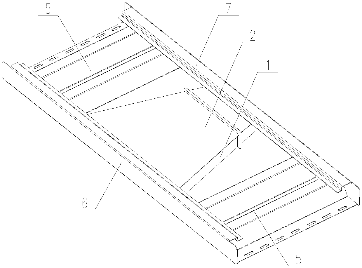
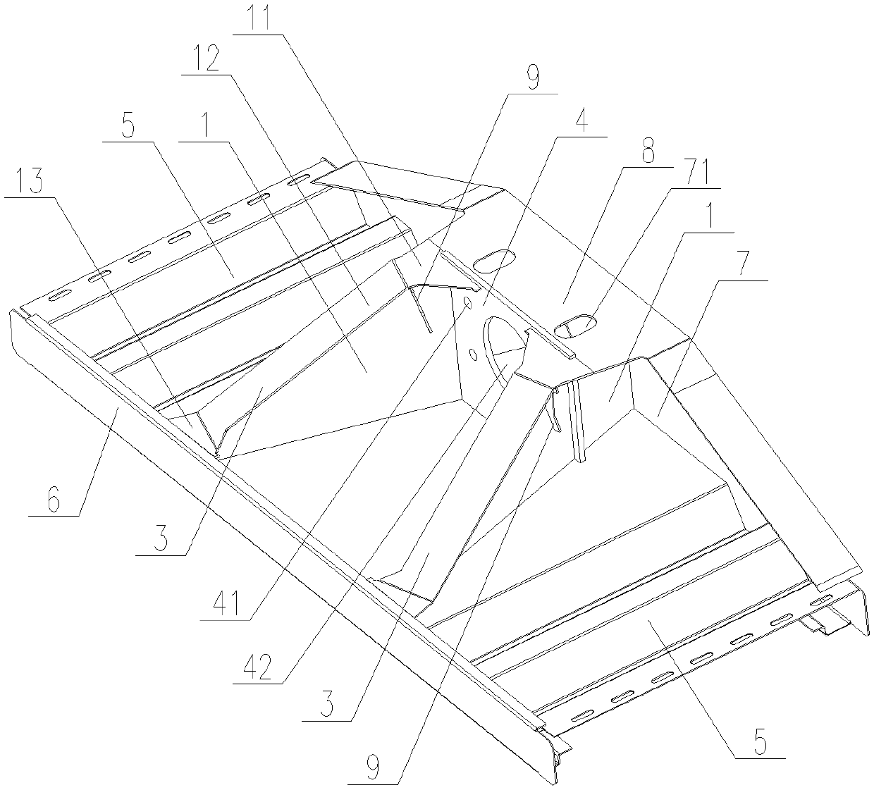
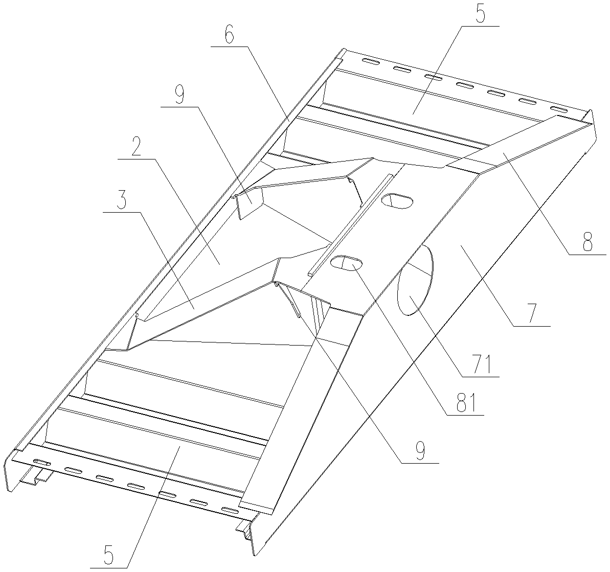
[0050] Example 1, such as Figure 1 to Figure 4 As shown, the laser-welded stainless steel coupler box mainly includes a pair of side webs 1 , an upper cover 2 and a lower cover 3 welded in sequence.

[0051] Among them, the web 1 is welded with the upper cover plate 2 and the lower cover plate 3 to form an integral box-shaped structure whose cross-sectional area gradually decreases from one end to the other end;

[0052] Coupler mounting plate 4, side corrugated plate 5, buffer beam 6 and rear end beam 7 are welded around the box structure;

[0053] The rear end beam 7 has an outwardly protruding rear end beam lower cover plate 8 which is respectively connected with the lower cover plate 3 and the coupler mounting plate 4 .

[0054] In the box-shaped structure composed of the web 1 , the upper cover plate 2 and the lower cover plate 3 , the cross-sectional area of ​​the end connected to the buffer beam 6 is the smallest, and the cross-sectional area of ​​the end connected to...


PUM


Abstract

The invention relates to a coupler box in a hollow box structure. Multiple lightweight design features are designed for parts of the coupler box, and accordingly structural rigidity and light weight are balanced. While structural rigidity and connection strength are guaranteed, the coupler box is made of stainless steel plates, so that the corrosion problem of carbon steel traction beams is solved thoroughly and painting is avoided. The coupler box comprises a pair of side webs, an upper cover plate and a lower cover plate, wherein the side webs, the upper cover plate and the lower cover plate are welded in sequence. The webs are welded to the upper and lower cover plates to form an integral box structure with the section area gradually decreasing from one end to the other end. A coupler mounting plate, side corrugated plates, a buffer beam, and a rear beam are welded to the periphery of the box structure. The rear beam is provided with rear beam lower cover plates which protrude out and are respectively connected with the lower cover plate and the coupler mounting plate. Connecting welds among the parts of the coupler box are all fixed by laser welding.

Description

technical field [0001] The invention is aimed at the improvement of the traction beam structure applied to rail vehicles, and belongs to the field of mechanical manufacturing. Background technique [0002] With the rapid popularization and promotion of domestic urban rail transit, higher design and use requirements are put forward for the traction beam which constitutes the main part of the drive system. [0003] For example, the traction beam used in light rail trains and subways is the central component that connects and transmits the driving force of the bogie to the car body, and is also the key equipment for power transmission to achieve fast and safe driving of the vehicle. The existing draw beam generally adopts carbon steel welded structure, because considering the corrosion of carbon steel, it is necessary to leave enough corrosion allowance for the carbon steel plate, thus increasing the weight of the coupler box itself, but also increasing the weight from the othe...

Claims


Application Information

Patent Timeline
Patent Type & Authority Patents(China)
IPC IPC(8): B61G9/22B61G7/00
Inventor 刘龙玺马云双王京军钟元木田洪雷牟晓莎
Owner CRRC QINGDAO SIFANG CO LTD
Why Eureka
Try Eureka