
Laser cladding method for roller

A laser cladding and rolling technology, which is applied in the coating process and coating of metal materials, can solve the problems of easy cracking and large thermal stress in the cladding layer, and achieve stable and reliable alloy composition and performance of the cladding layer. The effect of increasing the amount of steel and reducing the roll consumption

Active Publication Date: 2013-05-08
TSINGHUA UNIV
View PDF3 Cites 15 Cited by
  • Summary
  • Abstract
  • Description
  • Claims
  • Application Information

AI Technical Summary

Problems solved by technology

[0005] In the prior art, when laser cladding is performed on the surface of a large roll, due to the characteristics of rapid heating, rapid cooling and solidification, and large thermal stress during the laser cladding process, the cladding layer is extremely prone to cracks
Moreover, it is difficult to form a high-hardness, large-thickness and dense laser cladding layer on the surface of a large-size roll in the prior art.

Method used


Image

  • Laser cladding method for roller
  • Laser cladding method for roller
  • Laser cladding method for roller

Examples


Embodiment 1

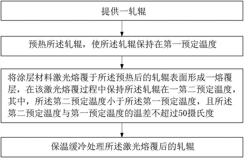
[0091] The selected material of the roll is semi-steel. The size specification of the roll is Φ900mm×1550mm×2750mm. The dimension specification of the roll refers to the diameter of the roll, the length of the working surface and the total length of the roll. The cladding layer is arranged on the working surface of the roll. The above-mentioned method of the present invention is used to carry out laser cladding repair treatment on the roll. Among them, the process parameters of the laser cladding process are:

[0092] (1) Laser cladding process: laser power 10KW, scanning speed 720mm / min, spot diameter 15x1.5mm, lap rate 50%, single pass cladding thickness 3.5mm, powder feeding width 15mm, cladding material is iron-based alloy powder.

[0093] (2) Heat treatment process parameters: roll preheating temperature 550-580°C, heating rate 200°C / hour, heat preservation for 1.5 hours; heating and heat preservation temperature during cladding process 520±20°C; 380±20°C for 5 hours ...

Embodiment 2

[0100] The differences between this embodiment and Embodiment 1 are:

[0101] The material of the roll is 70Mn2, and the specification is φ650mm×1250mm×2050mm. Using the method of the present invention to carry out laser cladding repair on the working surface of the roller, the process is as follows:

[0102] (1) Laser cladding process: laser power 8KW, scanning speed 600mm / min, spot diameter 15x1.5mm, lap rate 40%, single cladding thickness 3.0mm, powder feeding width 15mm;

[0103] (2) Heat treatment process parameters: roll preheating temperature 480-520°C, heating rate 150°C / hour, heat preservation for 1 hour; heating and heat preservation temperature 450±20°C during cladding; 380±20°C for 4 hours immediately after processing Keep warm, then turn off the power and cool slowly to room temperature.

[0104] In this embodiment, after the roll is repaired by laser cladding, a good high-speed steel alloy cladding layer is obtained. The cladding layer has a hardness of HRC61-6...


PUM

PropertyMeasurementUnit
Granularityaaaaaaaaaa
Melting pointaaaaaaaaaa
Thicknessaaaaaaaaaa

Abstract

The invention relates to a laser cladding method for a roller, which comprises the following steps of: providing a roller; preheating the roller so as to keep the surface of the roller at a first predetermined temperature; performing laser cladding on a coating material on the surface of the preheated roller to form a cladding layer; keeping the surface of the roller at a second predetermined temperature in the laser cladding process, wherein the second predetermined temperature is lower than the first predetermined temperature, and the temperature difference does not exceed 50 DEG C; and performing thermal insulation and slow cooling treatment on the roller after laser cladding.

Description

technical field [0001] The invention relates to a laser cladding method, in particular to a laser cladding method applied to rolls. Background technique [0002] Laser cladding began in the 1970s. It is a new type of material surface processing technology. It uses laser as an energy source to pre-set cladding materials on the surface of the base material to form a wear-resistant coating. [0003] High-speed wire rod roll is an important tool for wire rod production. The traditional high-speed wire rod roll is made of hard alloy powder sintered into a roll ring, which is mechanically combined with the roller to form a roll. my country has been the world's largest steel producer for many years in a row, with wire rod production accounting for 17.9% of total steel production. Annual production of wire needs to consume hundreds of tons of hard alloy roller rings. When the roller ring is broken or the size exceeds the standard due to wear, the roller ring will be scrapped, resu...

Claims


Application Information

Patent Timeline
IPC IPC(8): C23C24/10
Inventor 周明刘长隆张洪玉
Owner TSINGHUA UNIV
Learn More