Sub-rail isolating protective sleeve

A protective sleeve and rail technology, applied in the field of rail transit, can solve electric shock; if the other end of the conductive object is in contact with other equipment, a large current will enter, power supply equipment, communication signals will be affected, and the insulation between the rail and the earth will be damaged. problems, to achieve the effect of eliminating potential safety hazards, good vibration reduction, and strengthening the protection effect

Active Publication Date: 2013-05-08
QINGDAO CREATE ENVIRONMENT CONTROL TECH +1
View PDF5 Cites 1 Cited by
  • Summary
  • Abstract
  • Description
  • Claims
  • Application Information

AI Technical Summary

Problems solved by technology

Due to reasons such as construction, maintenance, and passengers leaving behind, there will be metal and other conductive foreign objects on the track bed, so metal or other conductive objects will enter the lower part of the track and touch the rail. It is not easy to find and eliminate during the inspection process, forming a potential safety hazard. The hazards are mainly manifested in: when a conductive object touches the rail, if the other end of the conductive object is connected to the ballast bed or the metal parts on the ballast bed, the insulation between the rail and the ground will be destroyed. , large current will flow into the ground through conductive objects and metal parts on the ballast bed, forming a huge "stray current", entering other equipment or related facilities, and even causing electric shock to passengers on the platform; if the other end of the conductive object is in contact with other equipment , there will be a large current entering the equipment, causing damage to the equipment; in addition, after the conductor touches the rail, it will also affect the power supply equipment and communication signals, especially when a large current flows, the contact point between the conductor and the rail will generate A large amount of heat will burn out the rails in severe cases and cause "rail burning" accidents, which directly affect driving safety

Method used


Image

  • Sub-rail isolating protective sleeve
  • Sub-rail isolating protective sleeve
  • Sub-rail isolating protective sleeve

Examples


Embodiment 1

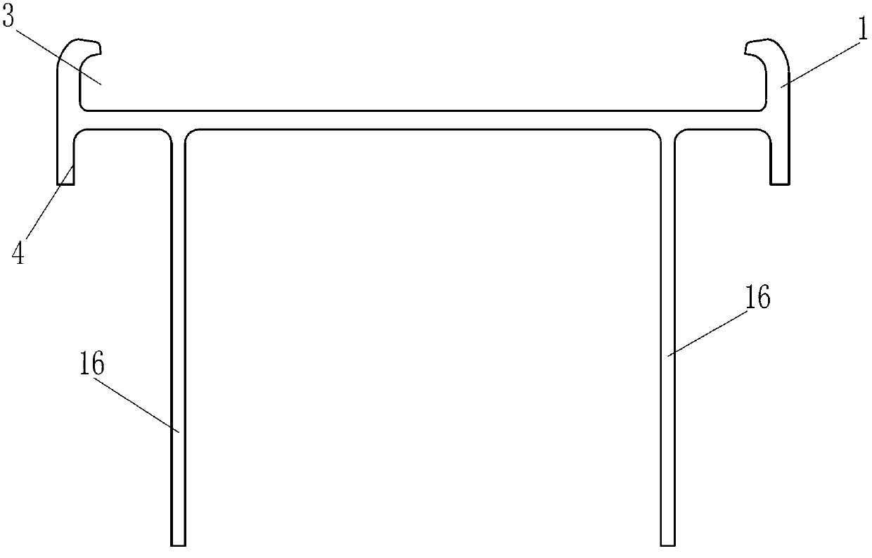
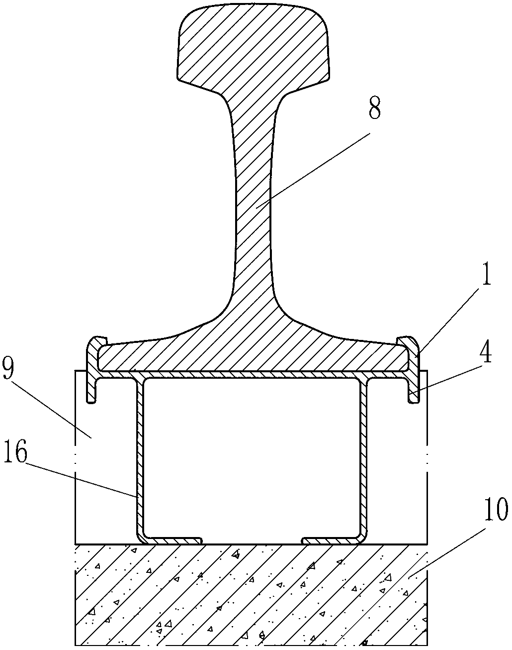
[0038] The structure of the isolation protection cover under the rail of the present invention, such as figure 1shown. The isolation protective cover body includes a fixed support 1 and a skirt, wherein the skirt includes two sub-skirts 16, and the fixed support 1 and the two sub-skirts 16 are integrally made of elastic insulating material, specifically rubber. The upper part of the fixed support 1 is provided with a card slot 3 whose size and shape correspond to the rail bottom of the rail. In addition, the bottom of the fixed support 1 is also provided with a water retaining structure 4. The water retaining structure is specifically a water retaining eaves. The sub-skirt 16 is placed on the inner side of the water retaining structure 4, and is symmetrically arranged on both sides of the bottom of the fixed support along the longitudinal direction of the rail.

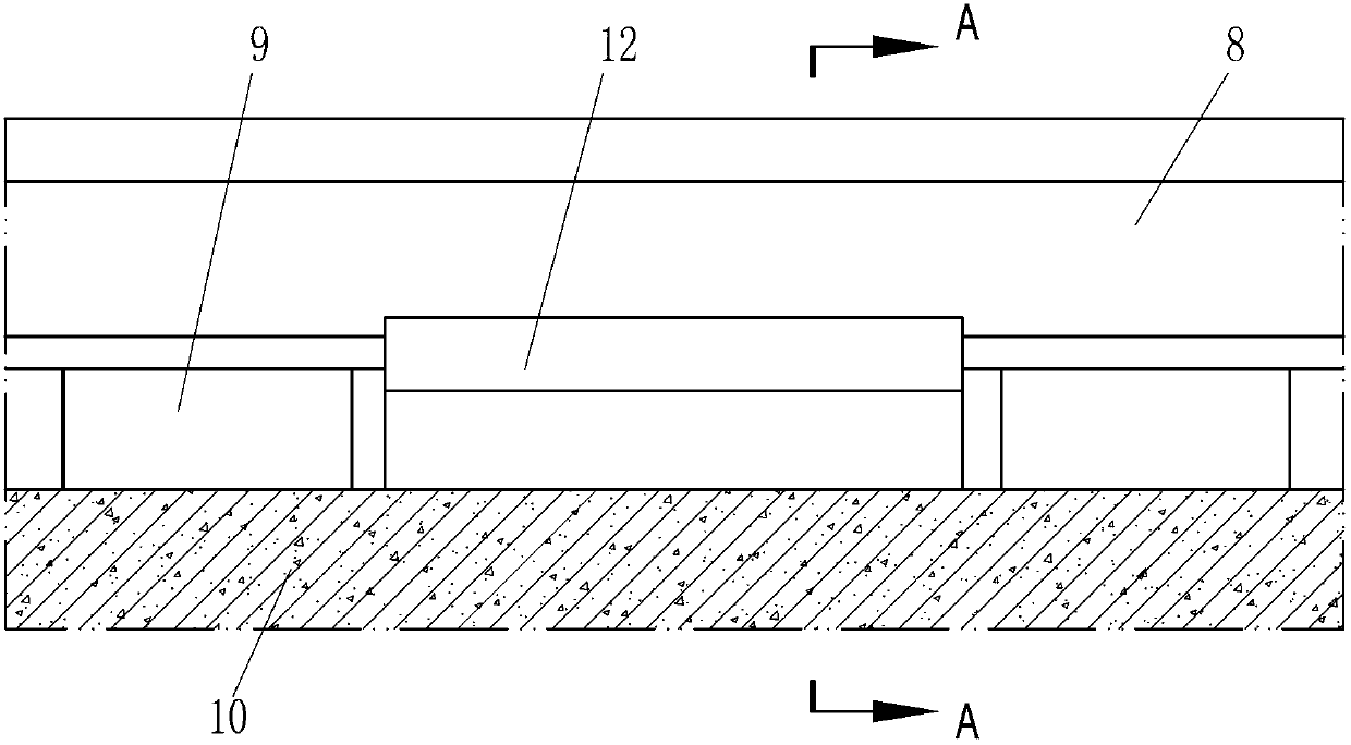
[0039] When applied, such as figure 2 and image 3 As shown, the under-rail isolation protective cover 12 of th...

Embodiment 2

[0045] like Figure 4 The difference between the isolation protection cover under the rail of the present invention and the first embodiment is that the isolation protection cover body includes a fixed support 1 and a skirt 2, and the fixed support 1 and the skirt 2 are made of different materials, wherein the fixed support The seat 1 is made of insulating hard rubber material, the skirt plate 2 is made of high elastic rubber material, and the two are vulcanized and connected into one. In addition, the sound shielding board 14 of the same material is integrated and symmetrically arranged on the fixed support 1, and the sound shielding boards respectively extend upward along both sides of the fixed support and gradually approach the center plane of the fixed support along the longitudinal direction of the rail. A cavity 15 along the longitudinal direction of the rail is formed below the fixed support. In addition, in order to improve the ability of the sound shielding board 14...

Embodiment 3

[0051] like Image 6 The difference between the under-rail isolation protective cover of the present invention and the first embodiment is that the isolation protective cover body includes two parts: an independent fixed support 1 and an apron 2 . The top of the fixed support 1 is provided with a card slot 3, and the bottom is provided with two rows of bosses 5 symmetrically along the longitudinal direction of the rail. The top of the skirt plate 2 is provided with a card slot 6 corresponding to the boss 5 . The cross-sectional profile of the boss 5 is "T" shape, and the shape of the slot 6 corresponds to the boss 5, and the boss 5 can be embedded in the slot 6, so as to realize the connection and limit of the fixed support 1 and the skirt plate 2. Water-retaining structures 4 are arranged on both sides of the skirt plate 2, and the water-retaining structures are specifically water-retaining eaves. Furthermore, a cavity 7 is provided in the apron 2 . The fixed support 1 is ...


PUM


Abstract

The invention relates to a sub-rail isolating protective sleeve. The sub-rail isolating protective sleeve comprises an isolating protective sleeve body, wherein the isolating protective sleeve body comprises a fixed support and a skirt plate; a clamping groove structure is arranged on the upper part of the fixed support and corresponds to the bottom of a steel rail; the skirt plate comprises two sub skirt plates; the two sub skirt plates are arranged on two sides of the lower part of the fixed support along the longitudinal direction of the steel rail respectively, or a cavity is formed in the skirt plate along the longitudinal direction or the vertical direction of the steel rail; and the skirt plate is arranged below the fixed support. The sub-rail isolating protective sleeve has the characteristics of diverse structure, convenience in installation and maintenance, high economic efficiency and wide application range; and after the sub-rail isolating protective sleeve is assembled at the bottom of the steel rail, the space between the steel rail between two sleepers and a ballast bed is relatively closed, so that foreign matters are prevented from entering the lower part of the steel rail, potential safety hazards are eliminated, and the market prospect is very wide.

Description

technical field [0001] The invention belongs to the field of rail transportation, and relates to a rail auxiliary device, in particular to a device for isolation and protection between the rail bottom and the ballast bed. Background technique [0002] With social development and scientific and technological progress, large and medium-sized cities pay more and more attention to the development of urban rail transit. Urban rail construction, especially the construction of underground railways, has also been launched one after another. The power supply mode of urban rail transit is to feed electric energy to the train in the form of overhead contact line or third rail through the DC traction substation arranged along the line, and use the running rail as the return line for return flow. The third rail is to lay a special light rail in parallel on one side of the rail. The shape is similar to the rail, and the shape of the section is also "I" shape, but the volume is much small...

Claims


Application Information

Patent Timeline
Patent Type & Authority Applications(China)
IPC IPC(8): E01B19/00
Inventor 尹学军孔祥斐付学智
Owner QINGDAO CREATE ENVIRONMENT CONTROL TECH
Why Eureka
Try Eureka