W-shaped rib channel cooling structure suitable for turbine blade backside cooling cavity

A technology of turbine blades and cooling structures, which is applied to the supporting elements of blades, engine elements, machines/engines, etc., can solve the problems of increasing the contact area of ​​cooling fluid, difficult cooling effect, and large flow loss, and achieves increased cooling effect, Simple structure, small flow resistance and flow loss effect

Inactive Publication Date: 2013-05-08
SHANGHAI JIAO TONG UNIV
View PDF9 Cites 23 Cited by
  • Summary
  • Abstract
  • Description
  • Claims
  • Application Information

AI Technical Summary

Problems solved by technology

[0003] After searching the existing technical literature, it is found that the Chinese patent application number is 200710118763.6, and the patent name is: a trapezoidal interlaced rib cooling blade suitable for gas turbine engines. The internal cooling cavity of the blade is covered with trapezoidal interlaced ribs, and the cooling fluid In the staggered rib channel formed between the staggered ribs, it flows alternately at 180° to the direction of the trailing edge of the blade. This cooling method can greatly increase the contact area between the cooling fluid and the solid, and at the same time, it can well increase t

Method used


Image

  • W-shaped rib channel cooling structure suitable for turbine blade backside cooling cavity
  • W-shaped rib channel cooling structure suitable for turbine blade backside cooling cavity
  • W-shaped rib channel cooling structure suitable for turbine blade backside cooling cavity

Examples


Embodiment

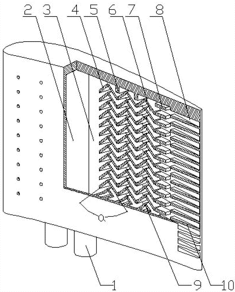
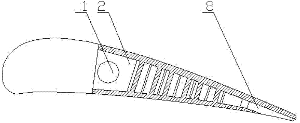
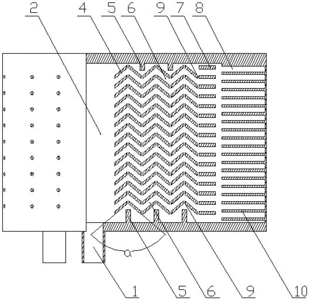
[0019] like figure 1 , figure 2 , image 3 and Figure 4 As shown, the present invention includes a cooling fluid inflow pipe 1, a blade rear cooling chamber 2, an inner wall 3 of the blade rear cooling chamber, a guide fin 4, a deflector fin 5, a W-shaped cooling channel 6, and a straight guide rib Slice 7, blade trailing edge slit 8, rib row spacing 9 and trailing edge slit rib 10, cooling fluid inflow pipe 1 communicates with cooling cavity 2 at the rear of the blade, and multiple rows of oblique guide ribs 4 connect with a row of The straight guide fins 7 are all arranged on the inner wall 3 of the cooling cavity at the rear of the blade, the trailing edge slit ribs 10 are arranged at the inner wall 3 of the cooling cavity at the rear of the blade near the trailing edge of the blade, and the flow blocking ribs 5 are arranged at the rear of the blade On the upper and lower end walls of the cooling chamber 2, the fin rows of multiple rows of oblique guide fins 4 are arra...


PUM

PropertyMeasurementUnit
Angleaaaaaaaaaa

Abstract

The invention discloses a W-shaped rib channel cooling structure suitable for a turbine blade backside cooling cavity and belongs to the field of turbomachinery design. The structure comprises a blade backside cooling cavity, inclined diversion fins, linear diversion fins and flow blocking fins; a plurality of rows of inclined diversion fins on the inner wall of the blade backside cooling cavity are distributed in a W-shaped manner; the linear diversion fins are arranged in a space between the last row of inclined diversion fins and blade tailing edge split seam; and a W-shaped cooling channel is formed by a space defined by the inclined diversion fins, linear diversion fins and the inner wall of the blade backside cooling cavity. According to the W-shaped rib channel cooling structure, the W-shaped rib channel cooling structure is arranged in the blade backside cooling cavity, the rib channel has diversion and acceleration effects on an inner fluid, and simultaneously the blades are reinforced with the arrangement of W-shaped fins. Besides, the structure is simple and reasonable in design, and is suitable for the internal cooling system of turbine blades of a gas turbine.

Description

technical field [0001] The invention relates to a cooling structure inside a gas turbine blade, in particular to a W-shaped rib channel cooling structure suitable for a cooling cavity at the rear of the turbine blade. Background technique [0002] With the development of modern gas turbine technology, higher requirements are put forward for the increase of turbine inlet temperature. How to improve the heat resistance of turbine blades is a key research direction in the field of gas turbine turbine design. At present, there are two main measures to improve the heat resistance of turbines. One is to develop new heat-resistant blade materials and coating materials, and the other is to study more effective turbine blade cooling structures. Compared with the second method, the first method has high research and development costs and a long period. Therefore, designing a more efficient turbine blade cooling structure is of great significance for further improving the heat resistan...

Claims


Application Information

Patent Timeline
IPC IPC(8): F01D5/18
Inventor 马超臧述升王建飞
Owner SHANGHAI JIAO TONG UNIV
Why Eureka
Try Eureka