System and method for visual inspection on burrs and stain defects of radio frequency identification (RFID) antennae

A visual inspection and antenna technology, applied in the field of RFID manufacturing, can solve problems such as high cost, unsuitable antennas without chips, and inability to clearly point out manufacturing process problems, achieving compact structure, easy operation, and easy quality control and adjustment. Effect

Active Publication Date: 2013-05-08
HUAZHONG UNIV OF SCI & TECH
View PDF4 Cites 34 Cited by
  • Summary
  • Abstract
  • Description
  • Claims
  • Application Information

AI Technical Summary

Problems solved by technology

[0004] At present, high-precision antenna pattern detection equipment is blank at home and abroad. Most of the existing technologies are manually (human eyes directly observe the printing of the antenna substrate) or semi-manual (human eyes observe the printing of the antenna substrate through the camera screen). ) to perform instruction detection, which is not only inefficient and costly, but also difficult to guarantee the accuracy and consistency of the detection conclusions, and greatly limits the development of the RFID antenna tag production industry
In recent years, as the requirements for detection automation have become higher and higher, there has also been a detection scheme for antenna quality that directly detects antenna performance and gives a detection conclusion, that is, directly uses a card reader to meas...

Method used


Image

  • System and method for visual inspection on burrs and stain defects of radio frequency identification (RFID) antennae
  • System and method for visual inspection on burrs and stain defects of radio frequency identification (RFID) antennae

Examples


Embodiment Construction

[0030] In order to make the object, technical solution and advantages of the present invention clearer, the present invention will be further described in detail below in conjunction with the accompanying drawings and embodiments. It should be understood that the specific embodiments described here are only used to explain the present invention, not to limit the present invention.

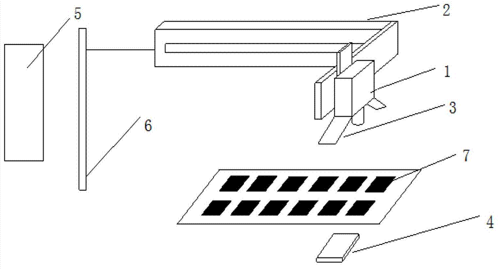
[0031] figure 1It is a schematic diagram of the overall structure of the visual inspection system for RFID antenna burrs and stain defects according to the present invention. As shown in the figure, the visual detection system for RFID antenna burrs and stain defects according to the present invention mainly includes a camera device 1, a three-degree-of-freedom mobile module 2, a strip light source 3, a backlight light source 4 and a visual detection device 5. The imaging device 1 is, for example, in the form of an industrial camera, which is installed on the three-degree-of-freedom mobile module ...


PUM


Abstract

The invention discloses a method for visual inspection on burrs and stain defects of radio frequency identification (RFID) antennae. The method comprises the following steps of: calibrating a camera device, and then shooting images of each RFID antenna to be inspected through the cooperation of the camera device and a strip-type or backlight source; acquiring the shot images of the antennae, and matching the acquired shot images with images of an antenna template to obtain pre-alignment information; taking off corresponding burrs and stain inspection areas from the images of the antennae according to regions of interest (ROI) on the images of the antenna template and the pre-alignment information; respectively carrying out binary processing on the inspection areas taken off from the images and the ROI, and then carrying out image subtraction; and carrying out blob analysis on residual images subjected to the image subtraction, and determining results of the burrs and the stain defects. The invention also discloses a system for carrying out the corresponding visual inspection. Through the method and the system, the inspection process of the burr/stain quality of the RFID antennae can be carried out efficiently and accurately, and the positions of the defects can be accurately positioned, so that the method and the system are particularly suitable for industrial processing and manufacturing processes of the RFID antennae.

Description

technical field [0001] The invention belongs to the field of RFID manufacturing, and more specifically relates to a visual inspection system and method for RFID antenna burr and stain defects. Background technique [0002] Video recognition, also known as RFID technology, also known as electronic tags, is a communication technology that identifies specific targets and reads and writes relevant data through radio signals. Its basic components include tags, readers and antennas. The tags are composed of coupling elements and chips. Each tag corresponds to a unique electronic code and is attached to the object to mark the target object; the reader is used to read and write or write tags information, while the antenna is used to transmit radio frequency signals between the tag and the reader. Because RFID technology does not need to establish mechanical or optical contact between the identification system and a specific target, and has the advantages of high-speed identificatio...

Claims


Application Information

Patent Timeline
IPC IPC(8): G01N21/88
Inventor 陈建魁钟强龙杨航
Owner HUAZHONG UNIV OF SCI & TECH
Why Eureka
Try Eureka