Method of probe and lead foot automatic aiming and probe station testing system thereof

A technology of probes and pins, which is applied in the field of testing equipment, can solve problems that cannot be ruled out, insufficient bonding, and low efficiency of manual alignment, and achieve the effect of enhancing bonding force and reducing contact time

Active Publication Date: 2013-05-08
SHANGHAI JIAO TONG UNIV
View PDF8 Cites 28 Cited by
  • Summary
  • Abstract
  • Description
  • Claims
  • Application Information

AI Technical Summary

Problems solved by technology

However, this technology does not provide the first self-alignment method for locating the device's pins with the probes
Therefore, this invention cannot realize true automatic alignment, and cannot eliminate the need for visual inspection by the operator through an automated device, so that the spatial positions and distances of the pins of the device under

Method used


Image

  • Method of probe and lead foot automatic aiming and probe station testing system thereof
  • Method of probe and lead foot automatic aiming and probe station testing system thereof
  • Method of probe and lead foot automatic aiming and probe station testing system thereof

Examples


Embodiment 1

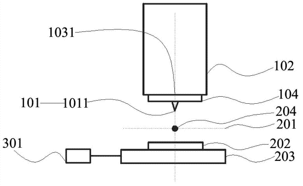
[0060] A probe station test system for automatic alignment of probes and pins:

[0061] Such as figure 1 As shown, a probe station testing system for automatic alignment of probes and pins includes: a probe 101 , a probe displacement device 102 , a probe frame 104 , a fixture 202 , a sample displacement device 203 , and a controller 301 .

[0062] Wherein, the probe 101 is used for contacting with the pin of the device under test, including a positioning test probe 1011, and the positioning test probe 1011 is a metal probe, a composite material probe, a one-dimensional material probe and / or a biological probe, fixed on the probe holder 104. The probe frame 104 is a support structure capable of fixing the probes, and is connected to the probe displacement device 102. The probe frame 104 is detachable, and the probes 101 can be replaced according to the relative positions of the pins of the device under test.

[0063] The probe displacement device 102 includes a driver, a powe...

Embodiment 2

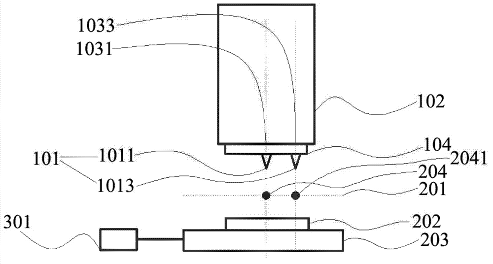
[0077] A probe station test system for automatic alignment of probes and pins:

[0078] Such as figure 2 As shown, a probe station testing system for automatic alignment of probes and pins includes: a probe 101 , a probe displacement device 102 , a probe frame 104 , a fixture 202 , a sample displacement device 203 , and a controller 301 .

[0079] Wherein, the probe 101 is used to contact the pins of the device under test, including a positioning test probe 1011 and an auxiliary positioning test probe 1013, the positioning test probe 1011 and the auxiliary positioning testing probe 1013 are metal probes, composite material probes The needles, one-dimensional material probes and / or biological probes are all fixed on the probe frame 104 . The probe frame 104 is a support structure capable of fixing the probes, and is connected to the probe displacement device 102. The probe frame 104 is detachable, and the probes 101 can be replaced according to the relative positions of the p...

Embodiment 3

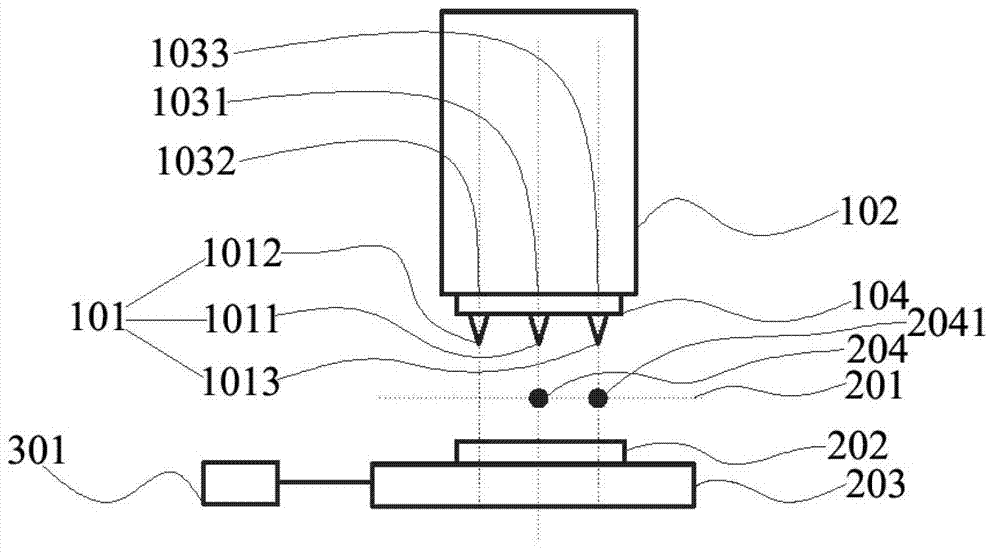
[0099] A probe station test system for automatic alignment of probes and pins:

[0100] Such as image 3 As shown, a probe station testing system for automatic alignment of probes and pins includes: a probe 101 , a probe displacement device 102 , a probe frame 104 , a fixture 202 , a sample displacement device 203 , and a controller 301 .

[0101] Wherein, the probes 101 are used to contact the pins of the device under test, including positioning test probes 1011 , auxiliary positioning testing probes 1013 and one or more non-positioning testing probes 1012 . Positioning test probes 1011, auxiliary positioning test probes 1013 and non-positioning test probes 1012 are all metal probes, composite material probes, one-dimensional material probes and / or biological probes, all of which are fixed on the probe frame 104 . The probe frame 104 is a support structure capable of fixing the probes, and is connected to the probe displacement device 102. The probe frame 104 is detachable,...


PUM

PropertyMeasurementUnit
Minimum spacingaaaaaaaaaa

Abstract

The invention discloses a method of probe and lead foot automatic aiming. Automatic aiming of the testing probe and the lead foot are achieved through six steps. The invention further discloses a probe station testing system of the probe and lead foot automatic aiming. The probe station testing system of the probe and lead foot automatic aiming comprises a movable probe displacement device, a probe frame, a probe, a fixture, a sample displacement device, a controlling device, a machinery supporting device, a signal transmission device and a power supply device. The probe frame and the probe are installed on the probe displacement device. The fixture is movable and is used for fixing a to-be tested device and a wafer. The controlling device is capable of setting up procedures of all the devices. The method of the probe and the lead foot automatic aiming and the probe station testing system of the probe and lead foot automatic aiming are low in cost and good in generality. The method of the probe and the lead foot automatic aiming and the probe station testing system of the probe and lead foot automatic aiming can test efficiently under the condition without damaging the to-be tested device and the wafer in short time. The method of the probe and the lead foot automatic aiming and the probe station testing system of the probe and lead foot automatic aiming can be applied widely in the survey of precise electricity of complex and high speed devices. Reliability of testing signal quality and testing results can be guaranteed. Testing time is shortened and cost of device manufacturing technology is reduced.

Description

technical field [0001] The invention relates to an automatic alignment method of semiconductor chip automatic test equipment, in particular to a method for automatic alignment of probes and pins and a probe station testing system thereof. It belongs to the field of testing equipment. Background technique [0002] In the electrical performance test of electronic devices, the electrical connection between the device pins and the test equipment needs to be realized through probes. In the semiconductor and optoelectronic industries that pursue miniaturization, it is difficult to Accurately touch the probes to the pins. For this reason, special probe station equipment has appeared in the field of test equipment, which is widely used in the research and development of precision electrical measurements of complex and high-speed devices, aiming to ensure quality and reliability, and reduce development time and device manufacturing costs. The core function of the probe station is t...

Claims


Application Information

Patent Timeline
IPC IPC(8): G01R1/067G01R1/073G01R31/00
Inventor 侯中宇潘元志
Owner SHANGHAI JIAO TONG UNIV
Why Eureka
Try Eureka