Optical scanning head drive control system based on hollow encoder and phase difference

A technology of drive control and optical scanning, which is applied in the field of optical scanning, can solve the problems of high precision and stability, and achieve the effect of improving errors

Active Publication Date: 2013-05-08
CHINA KEHAN LASER FUJIAN
View PDF5 Cites 6 Cited by
  • Summary
  • Abstract
  • Description
  • Claims
  • Application Information

AI Technical Summary

Problems solved by technology

However, the accuracy and stability requirements for the relative position between the optical lenses are much higher. Wit

Method used


Image

  • Optical scanning head drive control system based on hollow encoder and phase difference
  • Optical scanning head drive control system based on hollow encoder and phase difference
  • Optical scanning head drive control system based on hollow encoder and phase difference

Examples


Embodiment 1

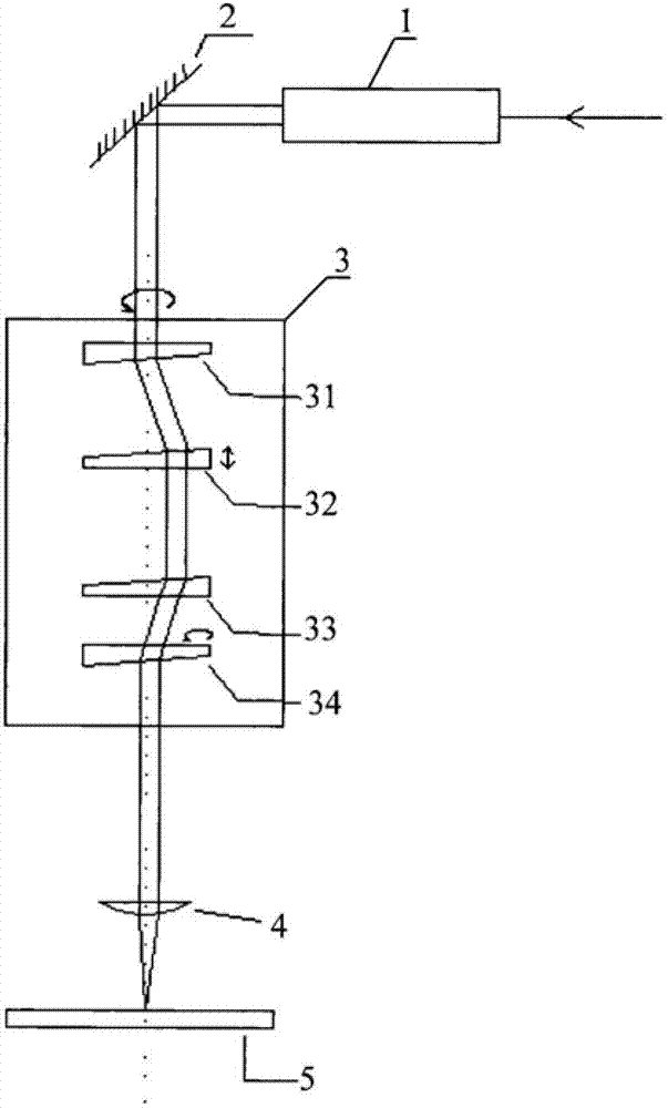
[0025] like figure 2 As shown, in order to directly collect the relative rotation angle of a pair of optical wedges 33 and 34, a hollow encoder is installed on the outer ring of the optical wedge to directly feed back the angle of the optical wedge.

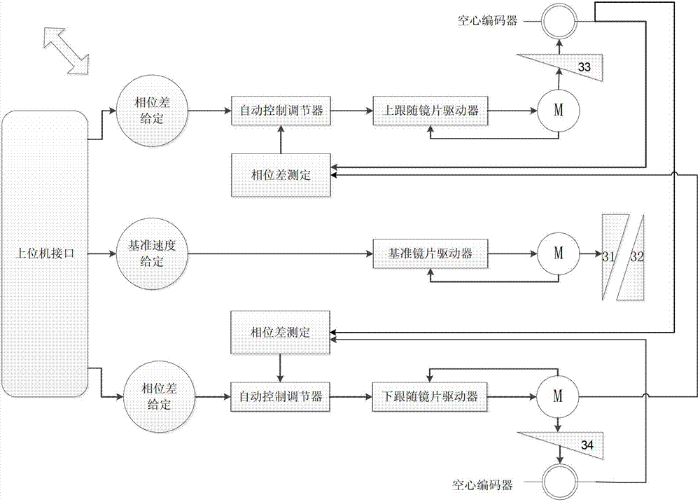
[0026] The system includes a host computer interface, an upper following mirror drive module, a reference mirror driver, a lower following mirror drive module, etc. The upper computer interface part is mainly responsible for exchanging information with the upper computer and processing the IO control signals from the outside, so as to coordinate the work of each lens driving part. When driving, the upper following mirror driving module drives the optical wedge 33 to rotate, the lower following mirror driving module drives the optical wedge 34 to rotate, and the reference mirror driver simultaneously drives the optical wedges 31 and 32 to rotate.

[0027] like figure 2 As shown in , the host computer interface receives the com...

Embodiment 2

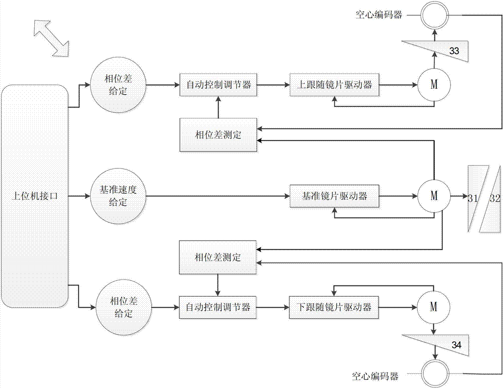
[0035] like image 3 As shown, compared with the first embodiment, in the second embodiment, the position feedback signal of the optical wedge 31 driven by the reference motor M is added. Since the reference motor operates at a constant speed, the position signal of the optical wedge 31 driven by it is fed back to the upper follower drive module and the lower follower drive module, and the precision of the deviation phase of its position is higher.

[0036] The position signal of the optical wedge 31 directly adopts the position signal fed back by the position sensor of the motor M.

[0037] like image 3 As shown, the outer rings of the optical wedges 33 and 34 are equipped with hollow encoders for feeding back the angle signals of each optical wedge. The phase difference signal between the optical wedges 31 and 33 is fed back to the automatic control regulator of the upper follower lens drive module, and the automatic control regulator compares the given phase difference s...

Embodiment 3

[0040] like Figure 4As shown, the third embodiment is compared with the second embodiment, a hollow encoder is installed on the outer ring of the optical wedge 31, and the position signal of the optical wedge 31 directly fed back by the hollow encoder is used as a reference signal.


PUM


Abstract

A drive control system of an optical scanning head comprises an upper following lens drive module, a benchmark lens drive module and a lower following lens drive module. The upper following lens drive module drives an upper following optical wedge to rotate, the lower following lens drive module drives a lower following optical wedge to rotate, and the benchmark lens drive module drives a benchmark optical wedge to rotate at a benchmark speed. The upper following lens drive module and the lower following lens drive module comprise an even automatic control adjuster, a phase difference measurement module, an upper following lens driver and a lower following lens. Locating signals of the optical wedges are collected by a hollow encoder, given phase difference signals are compared with phase difference signals collected between the upper following optical wedge and the lower following optical wedge, an error amount is obtained, a motor is driven to move according to motor rotation speed control signals newly generated by the error amount, rotation speed of the upper following optical wedge and the lower following optical wedge is changed until the error amount is in a permissible range.

Description

technical field [0001] The invention belongs to the field of optical scanning, and in particular relates to a driving control system of an optical scanning head based on a hollow encoder and a phase difference. Background technique [0002] At present, the optical scanning head generally realizes the offset operation of the laser beam by controlling four groups of optical lenses with different functions to rotate at high speed in strict accordance with certain rules. like figure 1 As shown, the commonly used laser processing equipment in the prior art includes a beam expander 1 , a mirror 2 , and a rotating light scanning device 3 . The scanning device that needs to be driven has four optical wedges 31, 32, 33, 34 that rotate synchronously around the laser optical axis. Let the holding of optical wedges 33 and 34 figure 1 In the middle position, the phase difference between the two is 0 degree, and by changing the phase difference between the optical wedges 33 and 34, the...

Claims


Application Information

Patent Timeline
IPC IPC(8): G02B26/10
Inventor 姜宝宁江浩赵华龙
Owner CHINA KEHAN LASER FUJIAN
Why Eureka
Try Eureka