Magnetic Antenna
A magnetic antenna and magnetic layer technology, applied to antennas, antenna components, loop antennas with ferromagnetic material cores, etc., can solve problems such as transmission and reception, magnetic antenna characteristic changes, and characteristic deviations, so as to reduce manufacturing costs and improve Mass productivity and the effect of suppressing variation
- Summary
- Abstract
- Description
- Claims
- Application Information
AI Technical Summary
Problems solved by technology
Method used
Image

Examples
Embodiment 1
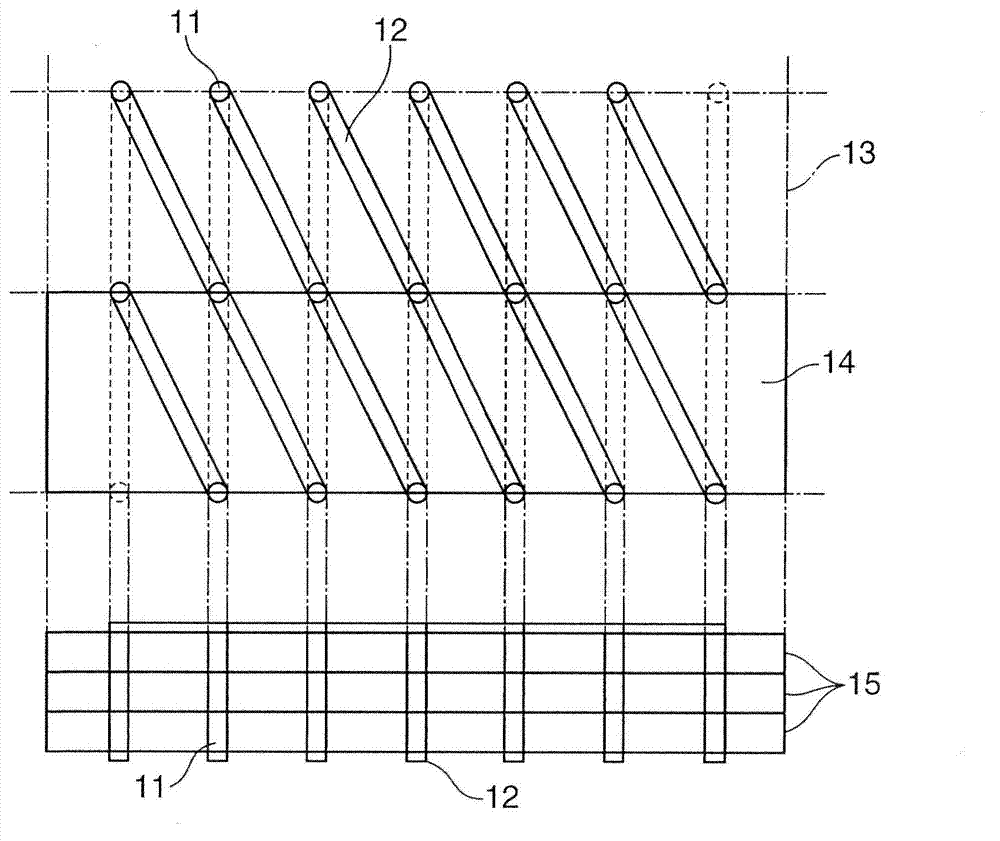
[0060] LTCC technology is used to manufacture the magnetic antenna of the present invention. First, the magnetic layer 15 is produced. In the manufacturing process of the magnetic layer 15, a ball mill was used to mix the Ni-Zn-Cu ferrite calcined powder (Fe) with a permeability of 100 at 13.56MHz after firing at a temperature of 900°C. 2 O 3 : 48.5 mol%, NiO: 25 mol%, ZnO: 16 mol%, CuO: 10.5 mol%. ) 100 parts (weight unit), 8 parts butyral resin (weight unit), 5 parts plasticizer (weight unit), 80 parts solvent (weight unit) to make the adhesive. The obtained adhesive liquid (slurry) was coated on a PET film using a doctor blade, and a sheet was formed into a square with a side length of 150 mm and a thickness of 0.1 mm during firing.
[0061] In addition, in the manufacturing process of the insulating layer 16, the same as the above, a ball mill was used to mix Zn-Cu ferrite calcined powder (Fe 2 O 3 : 48.5 mol%, ZnO: 41 mol%, CuO: 10.5 mol%) 100 parts, 8 parts of butyral resi...
Embodiment 2
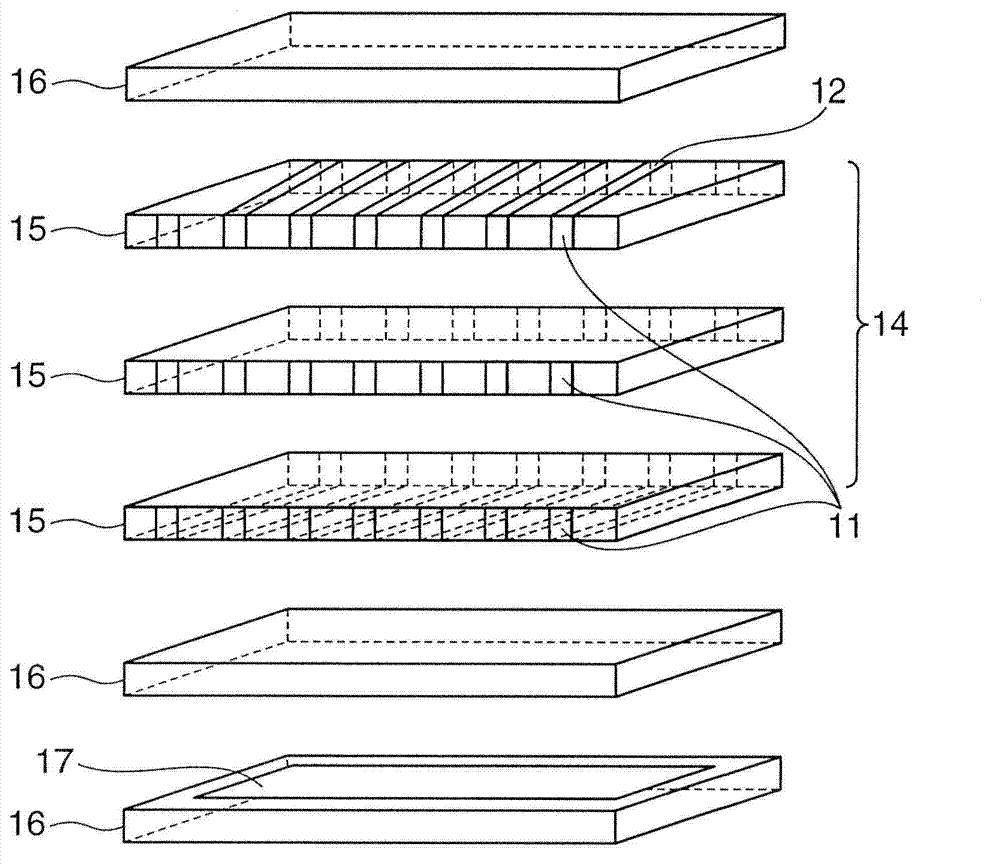
[0073] The same green sheet as the magnetic layer 15 as in Example 1 and a green sheet made of glass-based ceramics as the insulating layer 16 were used instead of the Zn-Cu ferrite. Such as image 3 As shown, five green sheets constituting the magnetic layer 15 are laminated, a through hole 11 is opened and silver paste is filled therein, and the silver paste is printed on two surfaces orthogonal to the through hole 11, thereby forming a coil 14.
[0074] Next, a green sheet constituting the insulating layer 16 is laminated on one surface of the coil 14. At this time, the conductive layer 17 is printed with silver paste on the insulating layer 16. In addition, another insulating layer 16 is laminated on the other surface of the coil 14. On the insulating layer 16, through holes 11 are opened for connection with both ends of the coil 14, and silver paste is filled in the insulating layer 16, and the On the surface of the insulating layer where the holes 11 are orthogonal to eac...
Embodiment 3
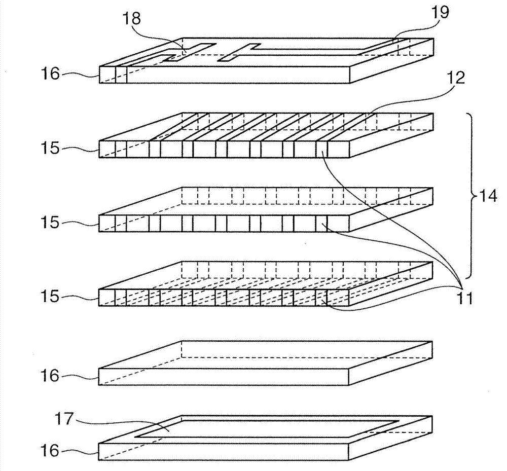
[0078] The same green sheet as the magnetic layer 15 and the green sheet as the insulating layer 16 as in Example 1 were used. Such as Figure 4 As shown, five green sheets constituting the magnetic layer 15 are laminated, a through hole 11 is opened thereon, and silver paste is filled therein, and silver paste is printed on both sides orthogonal to the through hole 11, thereby forming the coil 14.
[0079] Next, a green sheet constituting the insulating layer 16 is laminated under the coil 14. At this time, the conductive layer 17 is printed with silver paste on the insulating layer 16. Furthermore, a green sheet as the magnetic layer 15 is laminated under the insulating layer 16. A green sheet constituting the insulating layer 16 is laminated on the upper surface of the coil 14. On the upper surface of the insulating layer 16, through holes 11 are opened for connection with both ends of the coil 14, and silver paste is filled therein, and the surface layer of the insulating l...
PUM
| Property | Measurement | Unit |
|---|---|---|
| Resonance frequency | aaaaa | aaaaa |
| Resonance frequency | aaaaa | aaaaa |
| Resonance frequency | aaaaa | aaaaa |
Abstract
Description
Claims
Application Information
PatSnap Eureka turns technology decisions into work you can execute. Powered by our Innovation Knowledge Graph, it runs expert workflows across engineering, life sciences, materials and intellectual property. Get your review-ready output in minutes.


