

X-ray diagnostic system
An image diagnosis and X-ray technology, applied in the field of temperature rise suppression, can solve problems such as heat generation, and achieve the effects of suppressing heat generation, suppressing temperature rise, and reducing power input time
- Summary
- Abstract
- Description
- Claims
- Application Information
AI Technical Summary
Problems solved by technology
Method used
Image

Examples
no. 1 approach
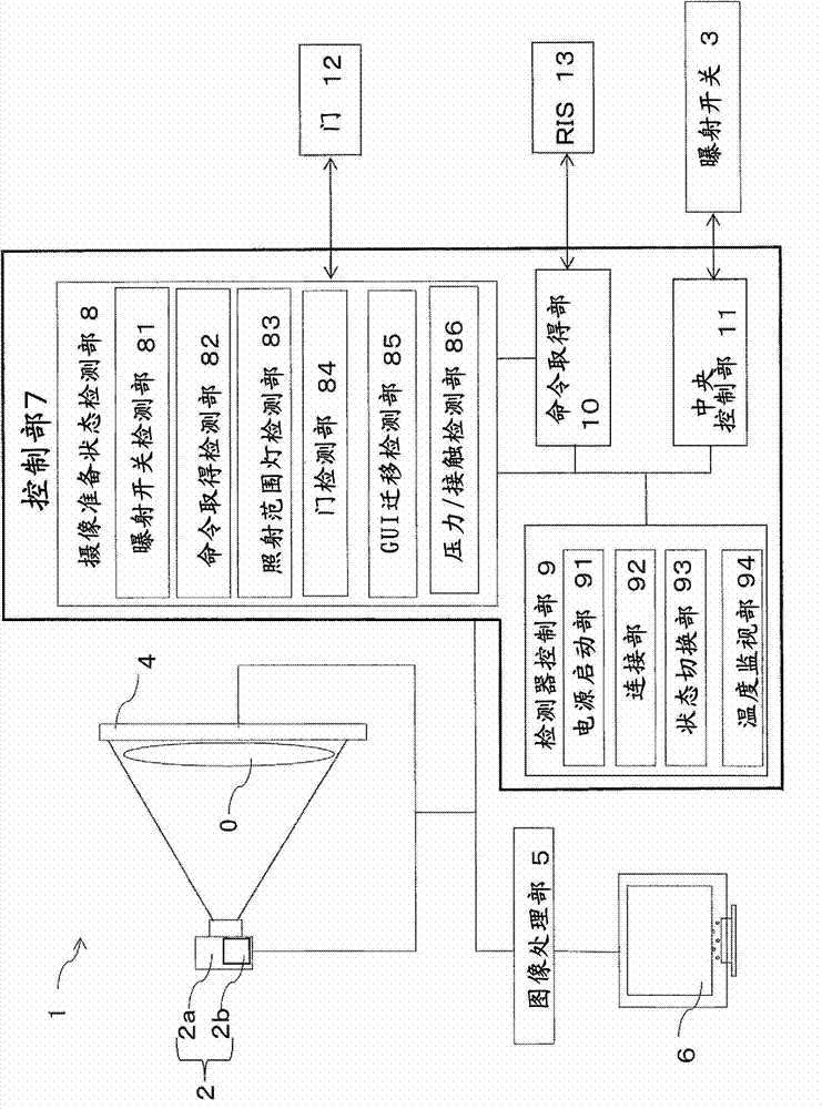
[0054] Next, based on Figure 6 to Figure 9 Processing related to the first embodiment will be described. Figure 6 It is a flowchart showing the flow of processing in the first embodiment. Figure 7 It is an explanatory diagram explaining the relationship between the internal temperature and the surface temperature of the X-ray flat panel detector 4 . Figure 8 It is a schematic diagram showing an example of warning display. Figure 9 It is a schematic diagram showing the power state of the X-ray plane detector 4 when continuously imaging the same subject and when different subjects are photographed, (a) shows the power state when continuously exposing the same subject, (b ) indicates the power state when the subject to be photographed is different.
[0055] The first embodiment is an embodiment in which the surface temperature of the X-ray plane detector 4 is continuously monitored from the start to the end of the system power supply, and the temperature is monitored at a...
no. 2 approach
[0106] Next, based on Figure 10 and Figure 11 Next, a second embodiment will be described. Figure 10 It is a schematic diagram showing the power state of the X-ray plane detector 4 in the second embodiment. Figure 11 It is a flowchart showing the flow of processing in the second embodiment. The second embodiment is an example in which temperature monitoring is performed at various stages of preparation for X-ray imaging, and is particularly an embodiment in which temperature monitoring is performed using an operation of an exposure switch as a trigger. Before explaining the second embodiment, based on Figure 10 The power state of the X-ray plane detector 4 in the second embodiment will be described.
[0107] When the main power supply is turned off, the input power is 0 (v). The power starting part 91 sends an instruction signal to put in (or stop) the main power, and when the main power of the X-ray plane detector 4 is turned on (or turned off), the power input part...
no. 3 approach
[0144] Next, based on Figure 12 A third embodiment will be described. The third embodiment is an example in which temperature monitoring is performed at each stage of preparation for X-ray imaging, and in particular, temperature monitoring is performed using transition of an imaging screen as a trigger. Figure 12 It is a flowchart showing the flow of processing in the third embodiment.
[0145] (steps S200, S201)
[0146] The system of the X-ray diagnostic apparatus 1 is started ( S200 ). Simultaneously with the system activation, the power supply activation unit 91 of the detector control unit 9 activates the main power supply unit 49 of the X-ray plane detector 4 ( S201 ).
[0147] (step S202)
[0148] When the order information acquisition unit 10 receives the order information through the barcode or the LAN connection, the order acquisition detection unit 82 detects the acquisition of the order information. The command acquisition detection unit 82 transmits a detec...
PUM
 Abstract
Description
Claims
Application Information