
Laser reflective coaxial measuring instrument

A technology of laser reflection and measuring instrument, which is applied in the direction of measuring devices, instruments, and optical devices, etc. It can solve the problems of delay in measurement results, reduce the efficiency of measurement, reduce the accuracy of coaxiality measurement, etc., achieve length reduction and improve measurement The effect of precision and low friction

Inactive Publication Date: 2015-09-09
NINGBO YINZHOU YUNFAN ENG CONSULTING
View PDF5 Cites 0 Cited by
  • Summary
  • Abstract
  • Description
  • Claims
  • Application Information

AI Technical Summary

Problems solved by technology

During the multiple transmissions of the gear, the slight gap between the meshing teeth of the gear will cause the delay of the measurement result. This delay will ignore some small fluctuations in the measurement value, thereby reducing the accuracy of the coaxiality measurement. At the same time , in order to overcome the measurement error caused by this delay, the measurement is only performed at a slower speed, which undoubtedly reduces the efficiency of the measurement

Method used


Image

  • Laser reflective coaxial measuring instrument
  • Laser reflective coaxial measuring instrument
  • Laser reflective coaxial measuring instrument

Examples


Embodiment Construction

[0025] The present invention will be further described below with reference to the drawings and embodiments.

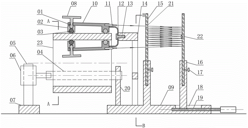
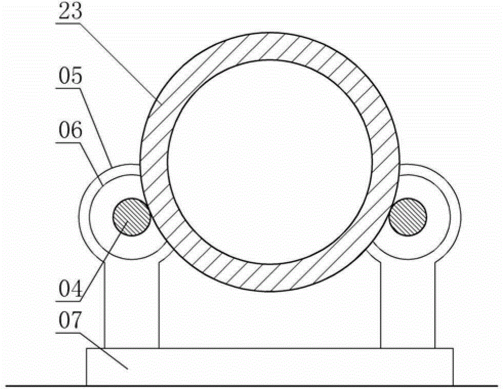
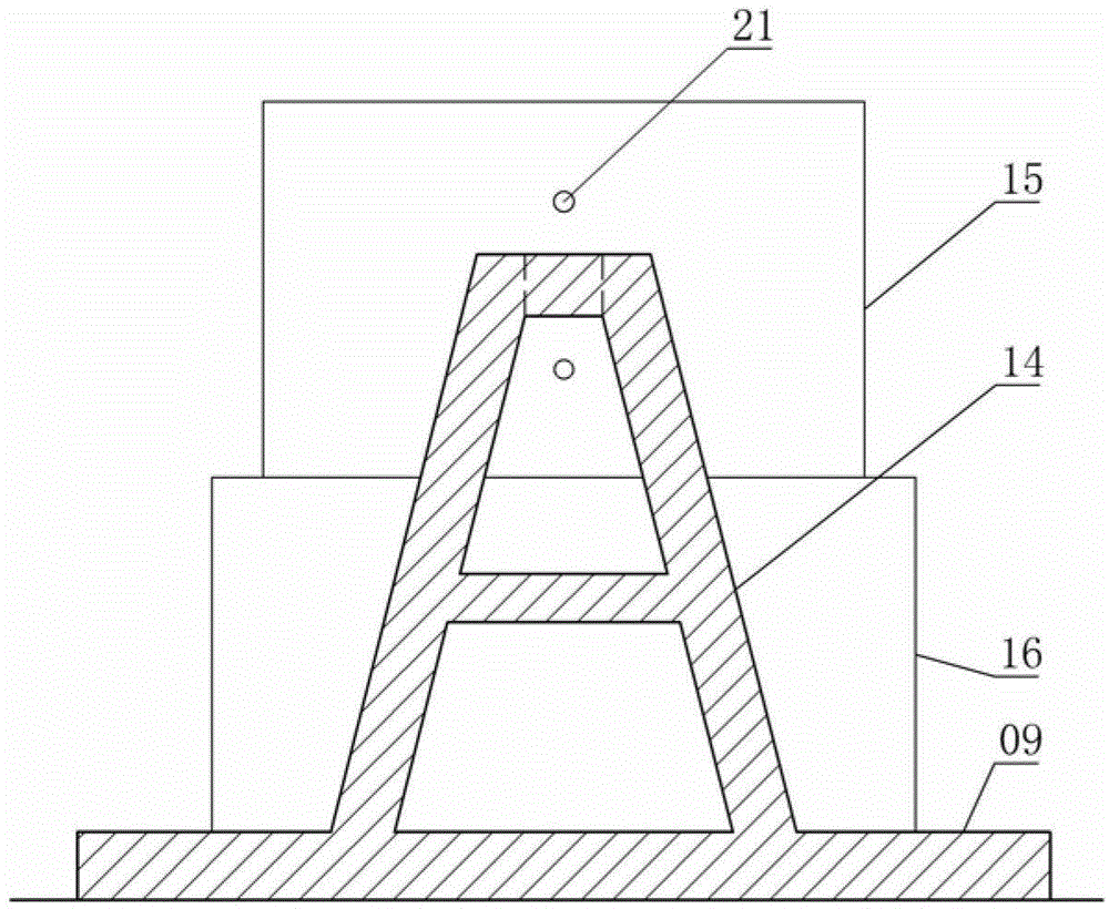
[0026] Laser reflection type coaxial measuring instrument, composed of adjusting rod 01, steel ball seat 02, steel ball 03, roller 04, motor frame 05, motor 06, motor seat 07, adjusting plate 08, mirror frame seat 09, clamp arm 10, The laser pointer 11, the spring sheet 12, the screw 13, the fixing frame 14, the flat mirror 15, the mirror frame 16, the fastening screw 17, the sliding groove 18, the adjusting handle 19, the shaft bracket 20, the entrance hole 21 and the projection target 22 are constituted.

[0027] Among them, the motor seat 07 and the mirror frame seat 09 are both metal cubes placed on a horizontal ground. The motor seat 07 is located on the left side of the mirror frame seat 09. The upper surface of the motor seat 07 has a pair of motors integral with the motor seat 07. The upper end of each motor frame 05 is fixed with a motor 06, and the rotating shaft...


PUM


Abstract

The invention relates to a machine part form and location tolerance measuring device, in particular to a laser reflection type coaxial measuring instrument. The laser reflection type coaxial measuring instrument is composed of an adjusting rod, a steel ball seat, steel balls, a roller, a motor frame, a motor, a motor seat, an adjusting plate, a mirror frame seat, arm locks, a laser pen, a spring piece, a bolt, a fixing frame, a plane mirror, a mirror frame, a fastening screw, a sliding groove, an adjusting handle, a shaft bracket, an incidence hole and a projection target. The U-shaped spring piece is connected with the top of the fixing frame into a whole through the bolt. The upper end and the lower end of the spring piece are respectively provided with an arm lock which is connected with the spring piece into a whole. Each steel ball is installed at the right end of each arm lock. The steel balls can rotate freely. A vertical thread through hole is formed in the left end of each arm lock. Threaded rods of the adjusting plate are matched with the thread through holes. Compared with the prior art, the machine part form and location tolerance measuring device is higher in measuring accuracy and measuring efficiency.

Description

Technical field [0001] The invention relates to a measuring device for the shape and position tolerance of mechanical parts, in particular to a laser reflection type coaxial measuring instrument. Background technique [0002] The "External Triangular Coaxial Measuring Instrument" with the patent number 200910060010.3 uses the combination of three limit plates and a dial indicator to measure the coaxiality of large pipe fittings. This device has the following defects: [0003] 1. This scheme does not have a reliable mechanical means to make the three limit plates close to the surface of the pipe and rotate, and can only be operated manually. For such an operation, the direction of force and the magnitude of the force are unstable, so It will undoubtedly reduce the accuracy of the measurement. [0004] 2. The reading of this solution depends on the measuring rod and the dial indicator, and the existing dial indicator is usually made of a gauge type universal length measuring tool usin...

Claims


Application Information

Patent Timeline
Patent Type & Authority Patents(China)
IPC IPC(8): G01B11/27
Inventor 梁德富
Owner NINGBO YINZHOU YUNFAN ENG CONSULTING
Learn More