Three-phase phase-locked loop method suitable for photovoltaic connected grid low voltage ride-through

A low-voltage ride-through, phase-locked loop technology, applied in the direction of phase angle between voltage and current, measuring electrical variables, measuring devices, etc., can solve the problem that the detection method is not considered, achieve simple feasibility and reduce the cost of grid connection , the effect of eliminating the measurement voltage deviation

Inactive Publication Date: 2013-05-15
HARBIN INST OF TECH
View PDF4 Cites 9 Cited by
  • Summary
  • Abstract
  • Description
  • Claims
  • Application Information

AI Technical Summary

Problems solved by technology

[0006] In order to solve the problem that the existing phase-locking technology needs to consider the influence of the zero point drift and the existing detection method does not consider the influence of the measured voltage offset on the voltage detection, a low-voltage grid-connected photovoltaic system is proposed. Three-phase phase-locked loop method for voltage ride-through

Method used


Image

  • Three-phase phase-locked loop method suitable for photovoltaic connected grid low voltage ride-through
  • Three-phase phase-locked loop method suitable for photovoltaic connected grid low voltage ride-through
  • Three-phase phase-locked loop method suitable for photovoltaic connected grid low voltage ride-through

Examples


specific Embodiment approach 1

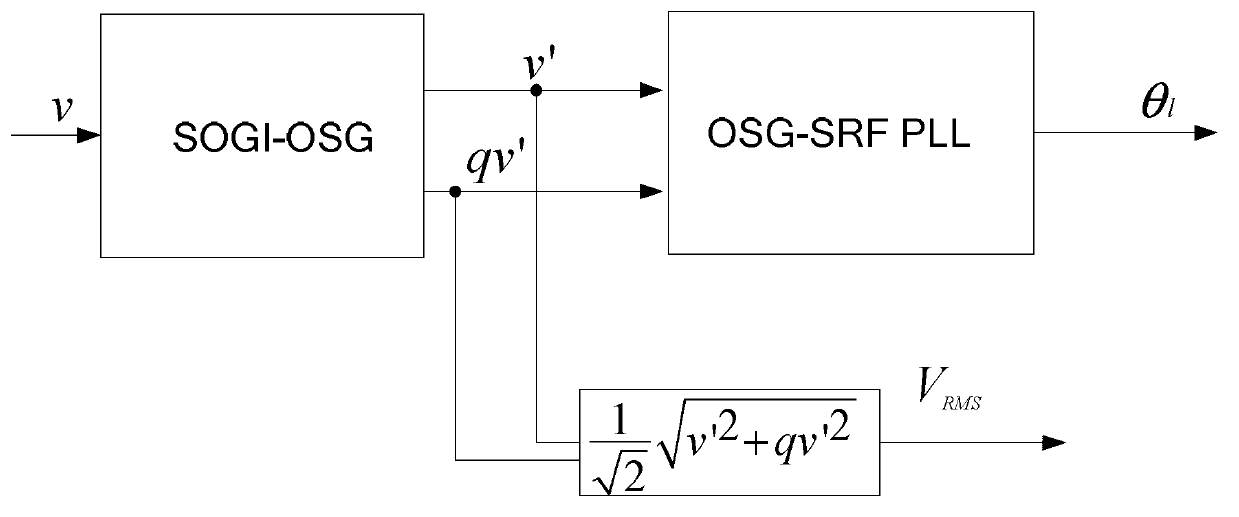
[0022] Specific implementation mode one: see image 3 , Figure 4 with Figure 9 To illustrate this embodiment, the specific process of a three-phase phase-locked loop method suitable for photovoltaic grid-connected low-voltage ride-through described in this embodiment is as follows:

[0023] Step A1: The grid voltage v is input to the second-order quadrature signal generator, and the second-order quadrature signal generator outputs two sinusoidal signals v' and qv' with a phase difference of 90°, and then step A2 and step A3 are performed simultaneously;

[0024] Step A2: Calculate the two sinusoidal signals v' and qv' obtained in step A1 to obtain the line voltage amplitude V RMS , the line voltage amplitude V RMS Converted to phase voltage amplitude V P , and then perform step A4;

[0025] Step A3: Input the two sinusoidal signals v' and qv' obtained in step A1 into the phase-locked loop, and the line voltage phase angle θ l Carry out locking and detection; set the li...

specific Embodiment approach 2

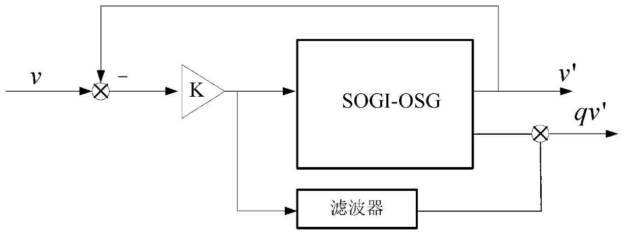
[0028] Specific implementation mode two: see figure 2 Describe this embodiment. This embodiment is a further definition of a three-phase phase-locked loop method suitable for photovoltaic grid-connected low-voltage ride-through described in the first embodiment. The second-order quadrature signal generator is set Second-order quadrature signal generator with low-pass filter.

[0029] The second-order quadrature signal generator described in this real-time mode is an improvement on the existing second-order quadrature signal generator (SOGI-OSG), that is, by adding a low-pass filter to eliminate the influence of voltage offset ,Such as figure 2 shown.

specific Embodiment approach 3

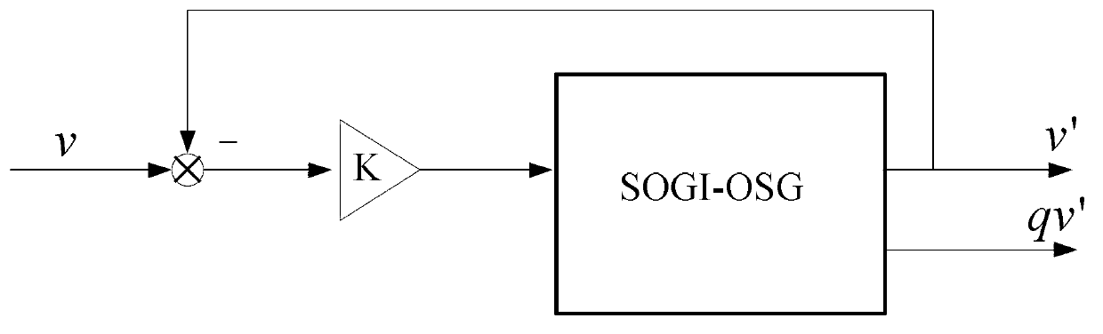
[0030] Specific implementation mode three: see Image 6 Describe this embodiment. This embodiment is a further definition of a three-phase phase-locked loop method suitable for photovoltaic grid-connected low-voltage ride-through described in the first embodiment. The grid voltage v in step A1 is input to The second-order quadrature signal generator, the method of the second-order quadrature signal generator outputting two sinusoidal signals v' and qv' with a phase difference of 90° is:

[0031] After the difference between the grid voltage v and the output signal v' of the second-order quadrature signal generator, the deviation signal ε is obtained. After the deviation signal ε passes through the amplifier, an amplified signal kε is obtained. The amplified signal kε is differenced with the signal qv' to obtain The signal is input to the multiplier, and the multiplier multiplies the signal with the phase-locked angular frequency ω′, and the obtained signal passes through the i...


PUM


Abstract

The invention discloses a three-phase phase-locked loop method suitable for photovoltaic connected grid low voltage ride-through, relates to the field of solar energy generating and power supplying, in particular to a three-phase phase-locked loop with the function of low voltage ride-through. The problems that affectation of zero wander is considered in existing phase-locked technology and affection on voltage detection due to measured voltage displacement is not considered in an existing detection method are solved. Firstly, voltage v of a power grid is input to a second order orthogonal signal generator and two sinusoidal signal (v' and qv') with a phase difference of 90 degrees are output. Secondly, the signal v' and the signal qv' are calculated to obtain a line voltage amplitude (VRMS) and the phase voltage amplitude (VRMS) is converted into a phase voltage amplitude VP. Thirdly, the signal v' and the signal qv' are input into the phase-locked loop and a line voltage phase angle theta 1 is locked and detected. The line voltage phase angle theta 1 is converted into a phase voltage phase angle theta p. Fourthly, based on the phase voltage amplitude VP and the phase voltage phase angle theta p, a inverter current control strategy is used for grid connecting and photovoltaic connected grid low voltage ride-through is achieved. The three-phase phase-locked loop method suitable for photovoltaic connected grid low voltage ride-through is suitable for photovoltaic power stations.

Description

technical field [0001] The invention relates to the field of solar power generation and power supply, in particular to a three-phase phase-locked loop with a low-voltage ride-through function. Background technique [0002] In recent years, with the expansion of the installed capacity of photovoltaic equipment, the proportion of solar power supply is increasing. Therefore, it is necessary to consider the impact of various operating states of photovoltaic power plants on the stability of the grid when the grid fails. The single-phase drop and double-phase drop in the three-phase unbalanced fault of the power grid have more and more serious impacts on photovoltaic grid connection. At present, as the power generation of photovoltaic power plants increases year by year, once these failures will lead to a large decrease in the output active power of the photovoltaic power plant, increase the difficulty of the recovery of the entire system, and may even aggravate the failure, causi...

Claims


Application Information

Patent Timeline
Patent Type & Authority Applications(China)
IPC IPC(8): G01R25/00
Inventor 丁宝张永明张功赵亮
Owner HARBIN INST OF TECH
Why Eureka
Try Eureka