Electric reactor

A reactor and electrical technology, applied in the direction of transformer/inductor magnetic core, etc., can solve the problems of large volume, weight, increased power loss, easy to generate noise, etc., achieve high glass transition temperature, reduce power loss, and improve linearity degree of effect

Inactive Publication Date: 2013-05-15
瑞力盟数控技术(常州)有限公司
View PDF0 Cites 2 Cited by
  • Summary
  • Abstract
  • Description
  • Claims
  • Application Information

AI Technical Summary

Problems solved by technology

[0002] In the traditional design scheme, the overall iron core uses oriented silicon steel sheet, coupled with the limitation of low saturation magnetic density of oriented silicon steel, the actual magnetic density Bm of the reactor is relatively low, so the linearity of the product is poor (generally 1.2 times) , the volume and weight of the product are relatively large, and the cost is relatively high
Reactors made of oriented silicon steel are mainly suitable for low-frequency fields, and only have obvious effects on low-order harmonics. When high-order harmonics or high-frequency DC components exist in the system circuit, the filtering effect of oriented silicon steel reactors is not good. Obvious, and it is easy to generate noise, the iron core column heats up very high, and the power loss increases
Reactors made of oriented silicon steel, in the production process, mostly rely on manual stacking operations, the process is complicated, and the production efficiency is low
[0003] At present, the processing method of oriented silicon steel sheet generally adopts the single sheet stamping method, the burr of the silicon steel sheet is relatively large, and there are unavoidable size errors between the sheets, and in the process of manufacturing the reactor, the method of manual stacking is adopted. The uneven thickness of the final processed block iron core causes the instability of the air gap height of the reactor, so that the consistency of the performance of the reactor is poor

Method used


Image

  • Electric reactor

Examples


Embodiment Construction

[0014] The preferred embodiments of the present invention will be described in detail below in conjunction with the accompanying drawings, so that the advantages and features of the present invention can be more easily understood by those skilled in the art, so as to define the protection scope of the present invention more clearly.

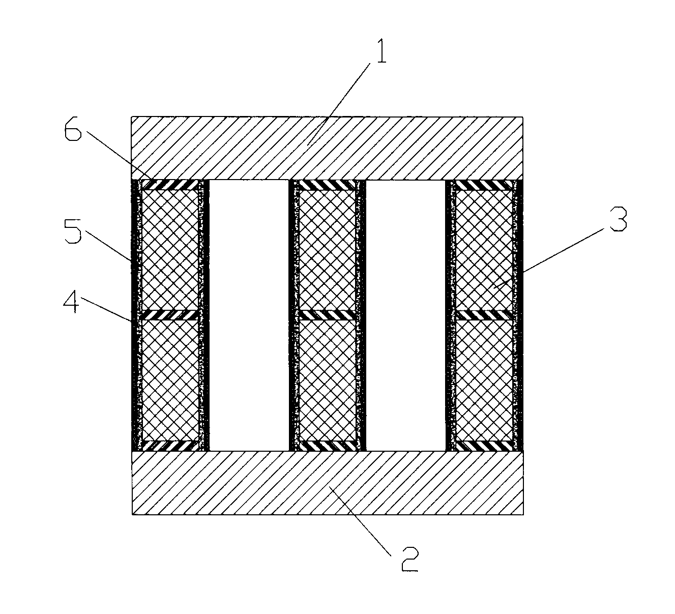
[0015] see figure 1 , the embodiment of the present invention includes:

[0016] A reactor, comprising an upper iron core 1, a lower iron core 2 and a nanocrystalline iron core post 3 arranged between the upper iron core 1 and the lower iron core 2, the outer layer of the nanocrystalline iron core post 3 is coated with The tensile layer 4 and the nanocrystalline iron core column 3 are provided with several air gaps 6 .

[0017] The upper iron core 1 and the lower iron core 2 are electrical silicon steel cores, and the upper iron core 1, the lower iron core 2 and the nanocrystalline iron core column 3 are connected by welding, and the nanocrystal...


PUM


Abstract

The invention discloses an electric reactor which comprises an upper iron core, an iron core and a nanocrystalline iron core column arranged between the upper iron core and the lower iron core, wherein the a stretch-resistant layer is coated on the outer layer of the nanocrystalline iron core column which is provided with a plurality of gas gaps. According to the electric reactor, the nanocrystalline iron core column is utilized, the size of a product is reduced, power consumption of the product is reduced, and linearity, consistency and high-frequency direction current carrier resistant performance are improved. The stretch-resistant layer is coated on the outer layer of the stretch-resistant layer through a resin pouring layer, vibration of the electric reactor is reduced obviously, noise is reduced obviously, the resin pouring layer further has good heat resistance performance simultaneously, virtrification temperature of the electric reactor is high, and softening can not occur under 180 DEG C. the fact that the temperature rise cannot achieve the virtrification temperature of the resin pouring layer caused by the heating of the nanocrystalline iron core of the electric reactor, therefore the problem that the resin pouring layer is softened is resolved in essence, and quality of the product of the electric reactor is guaranteed.

Description

technical field [0001] The present invention relates to a reactor. Background technique [0002] In the traditional design scheme, the overall iron core uses oriented silicon steel sheet, coupled with the limitation of low saturation magnetic density of oriented silicon steel, the actual magnetic density Bm of the reactor is relatively low, so the linearity of the product is poor (generally 1.2 times) , The volume and weight of the product are relatively large, and the cost is relatively high. Reactors made of oriented silicon steel are mainly suitable for low-frequency fields, and only have obvious effects on low-order harmonics. When high-order harmonics or high-frequency DC components exist in the system circuit, the filtering effect of oriented silicon steel reactors is not good. Obviously, and it is easy to generate noise, the iron core column heats up very high, and the power loss increases. Reactors made of oriented silicon steel, in the manufacturing process, mostl...

Claims


Application Information

Patent Timeline
IPC IPC(8): H01F27/26H01F27/24
Inventor 葛玉江
Owner 瑞力盟数控技术(常州)有限公司
Why Eureka
Try Eureka