H-plane waveguide power divider

A technology of power splitter and surface wave, which is applied in the direction of waveguide devices, electrical components, connecting devices, etc., can solve the problems of device volume and design difficulty, and achieve the effect of low processing difficulty, small volume and simple structure

Active Publication Date: 2013-05-15
成都赛纳赛德科技有限公司
View PDF4 Cites 11 Cited by
  • Summary
  • Abstract
  • Description
  • Claims
  • Application Information

AI Technical Summary

Problems solved by technology

Especially in the miniaturization design of multi-channel power division network, the phase compensation circuit will greatly increase the device size and design difficulty

Method used


Image

  • H-plane waveguide power divider
  • H-plane waveguide power divider
  • H-plane waveguide power divider

Examples


Embodiment 1

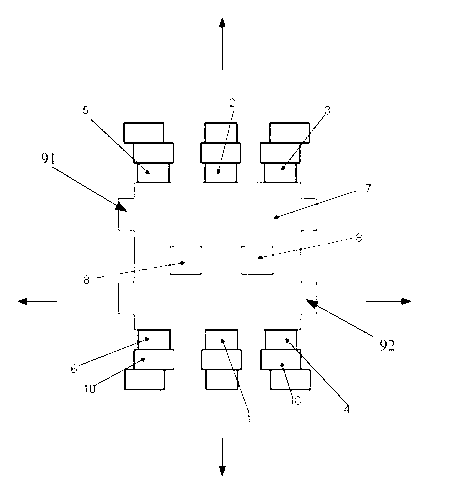
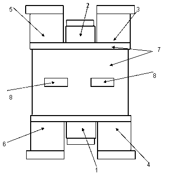
[0031] Such as figure 2 As shown, an H-plane waveguide power divider includes a coupling cavity 7, an input port 1 connected to the coupling cavity 7, an isolation port B4, an isolation port C6, an isolation port A2, an output port A3, and an output port B5. The input port 1 is located at the front end of the coupling cavity 7, the isolation port A2 is located at the rear end of the coupling cavity 7, the front end and the rear end are two opposite sides of the coupling cavity 7, and the isolation port B4 and the isolation port C6 are respectively located at the input On both sides of the port 1, the output port A3 and the output port B5 are respectively located on both sides of the isolation port A2. Transition sections 10 are provided on the input port 1 , the isolation port B4 , the isolation port C6 , the isolation port A2 , and the output port A3 and the output port B5 . The vertical component of the electric field at the center of at least three of the input port 1, th...

Embodiment 2

[0040] Such as Figure 4 . The only difference from Example 1 is that two metal bosses 9 are used instead of two grooves 8 .


PUM


Abstract

The invention discloses an H-plane waveguide power divider. The H-plane waveguide power divider comprises a coupling cavity, an input port, an isolation port B, an isolation port C, an isolation port A, an output port A and an output port B, wherein the input port, the isolation port B, the isolation port C, the isolation port A, the output port A and the output port B are communicated with the coupling cavity; and the input port is located at a front end face of the coupling cavity, the isolation port A is located at a rear end face of the coupling cavity, the front end face and the rear end face are two mutually-symmetrical opposite faces of the coupling cavity, the isolation port B and the isolation port C are respectively located at the two sides of the input port, and the output port A and the output port B are respectively located at the two sides of the isolation port A. The H-plane waveguide power divider further has the characteristics of simple structure, small volume and low processing difficulty. The H-plane waveguide power divider can be widely applied to the military and civilian fields of antenna arrays, phased-array radar, power synthesis, missile guidance, communications and the like.

Description

technical field [0001] The invention relates to a power splitter, in particular to a two-way power splitter with an equal-phase H-plane waveguide. Background technique [0002] The power splitter is a common component in modern microwave communication and military electronic systems. Due to its high power capacity and low insertion loss, waveguide power splitters are widely used. The two-way waveguide power splitter can be used alone, or can be connected in series to form a multi-way power splitting network, which is used in the fields of phased array radar, antenna array, and power combination. The existing two-way waveguide power splitter mainly includes E-plane T-shaped branch, H-plane T-shaped branch, waveguide magic T, H-plane waveguide crack bridge, etc. Among them, due to the low isolation between the two output terminals of the first two devices, the mismatch of any output port will seriously affect the amplitude and phase accuracy of power distribution. There is ...

Claims


Application Information

Patent Timeline
Patent Type & Authority Applications(China)
IPC IPC(8): H01P5/16
Inventor 王清源谭宜成丁金义
Owner 成都赛纳赛德科技有限公司
Why Eureka
Try Eureka