
Forced cooling method for wind power cast

A technology for forced cooling and casting, applied in the field of forced cooling of wind power castings, can solve the problems of reduced forced cooling effect of cold iron, difficulty in heat dissipation of molding sand, and inability to meet UT flaw detection level, etc., to prevent improper placement, simple structure, and processing and manufacturing handy effect

Inactive Publication Date: 2013-05-22
KOCEL GROUP +1
View PDF4 Cites 6 Cited by
  • Summary
  • Abstract
  • Description
  • Claims
  • Application Information

AI Technical Summary

Problems solved by technology

The internal molding sand of the casting is less, and it is difficult to dissipate heat from the molding sand under high-temperature molten iron. The cold iron placed in the core is always in a high-temperature state, so the forced cooling effect of the cold iron is greatly reduced, resulting in continuous distribution of shrinkage and shrinkage cavities in the middle of the casting , can not meet the UT flaw detection level
There is currently no solution to this problem

Method used


Image

  • Forced cooling method for wind power cast
  • Forced cooling method for wind power cast

Examples


Embodiment Construction

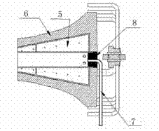
[0022] A method for forced cooling of wind power castings, comprising the steps of:

[0023] a. Making heat exchangers;

[0024] b. When producing sand cores, embed the core iron in the molding sand, and at the same time, the two ends of the core iron leak out of the molding sand, that is, the end faces of the core iron and the sand core are on the same surface, and at the same time ensure that the two ends of the core iron is unimpeded;

[0025] c. If figure 2 Shown: put the heat exchanger 5 into the inner cavity of the sand core 6;

[0026] d. When molding, pre-embed a ceramic tube 7 of ?

[0027] e. When closing the box, after putting the above sand core into the mold cavity, connect the core iron of the sand core and the pre-embedded ceramic tube in the mold cavity through a ceramic tube to ensure that the three are completely unblocked;

[0028] f. use core sand 8 to fill the rear part of the heat exchanger;

[0029] g. After closing the box, connect the above-menti...


PUM

PropertyMeasurementUnit
sizeaaaaaaaaaa

Abstract

The invention relates to a forced cooling method for a wind power cast, in particular to a forced cooling method for a wind power cast. The method comprises the following steps of manufacturing a heat exchanger, when producing a sand core, embedding core iron into casting san, and placing the heat exchanger into an inner cavity of the sand core; embedding a ceramic pipe communicated with the heat exchanger into the central position of the end face of a core head of the sand core during modeling, and enabling the ceramic pipe to be connected with the outside of a sand box; when the box is closed, after placing the sand core into a cavity, connecting the core iron of the sand core and the ceramic pipe embedded in the cavity through the ceramic pipe, and filling the core sand into the rear portion of the heat exchanger; after the box is closed, communicating the ceramic pipe and a compressed air port through a flexible hose; and during pouring, when iron liquid of the cavity is full, feeding gas into the heat exchanger. The forced cooling method for the wind power cast is unique in process, the cast is cooled through air blowing by utilizing the heat exchanger, heat dissipation of the sand core of the inner cavity is accelerated, iron liquid crusting is accelerated while vibration ramming is utilized to enable the inside of the cast to be compact, and the requirements for flaw detection can be met.

Description

technical field [0001] The invention relates to a cooling method in the cast iron casting process, in particular to a forced cooling method for wind power castings. Background technique [0002] The shaft casting is the key part connecting the engine and the base of the wind turbine. It is a cantilever structure in the generator set, which not only bears the weight of about 70 tons from the generator and the impeller, but also bears the instantaneous impact load brought by the uncontrollable wind. It is a key component in wind power castings. The appearance size of thick-walled wind power ductile iron castings is φ1330~φ1800, and the length is 2500~5000mm. It is a slender tubular part with a height-to-diameter ratio of 2~4. The heat dissipation conditions of this type of casting are the worst, and the internal quality of the casting to be drilled and the area subjected to pressure and torque must reach UT2 level. After the casting is poured, the actual shrinkage of the molt...

Claims


Application Information

Patent Timeline
Patent Type & Authority Applications(China)
IPC IPC(8): B22D27/04
Inventor 李旭刘利平陈洪涛张俊勇
Owner KOCEL GROUP
Learn More