Combined type rubber shock absorber

A technology of rubber shock absorber and rubber shock absorber, which is applied in the direction of spring/shock absorber, spring assembly composed of several springs, springs, etc., can solve the problem of limited bonding strength, loss of shock absorber function, T Eliminate the tearing of the type rubber vibration damping pad, etc., to achieve the effect of strong designability and enhanced reliability

Active Publication Date: 2013-05-22
AEROSPACE RES INST OF MATERIAL & PROCESSING TECH +1
View PDF2 Cites 41 Cited by
  • Summary
  • Abstract
  • Description
  • Claims
  • Application Information

AI Technical Summary

Problems solved by technology

[0003] Although the traditional T-shaped rubber shock absorber structure has the functions of vibration isolation and buffering, it is difficult to design its axial and lateral stiffness to three-way equal frequency when the equipment installation space and interface size are limited, and the designability is not good. Strong, and with the development of equipment in the direction of high speed, heavy load and high power, the mechanical environment of each subsystem on the equipment, such as control system, precision instrument, instrument system, etc., is getting worse and worse, making the T-type reducer The stress concentration phenomenon in the step part of the vibration pad is intensified, which is easy to cause the tear of the T-shaped rubber vibration damping pad
The metal-rubber composite shock absorber structure is designed to achieve three-way equal frequency, which is convenient to use and install. However, since the silicone rubber commonly used in shock absorbers is a type of non-polar polymer damping material, the bonding strength between rubber and metal is limited. Debonding is prone to occur under large dynamic loads, which may cause the shock absorber to completely lose its damping function, resulting in catastrophic consequences for the damped equipment

Method used


Image

  • Combined type rubber shock absorber
  • Combined type rubber shock absorber
  • Combined type rubber shock absorber

Examples


Embodiment 1

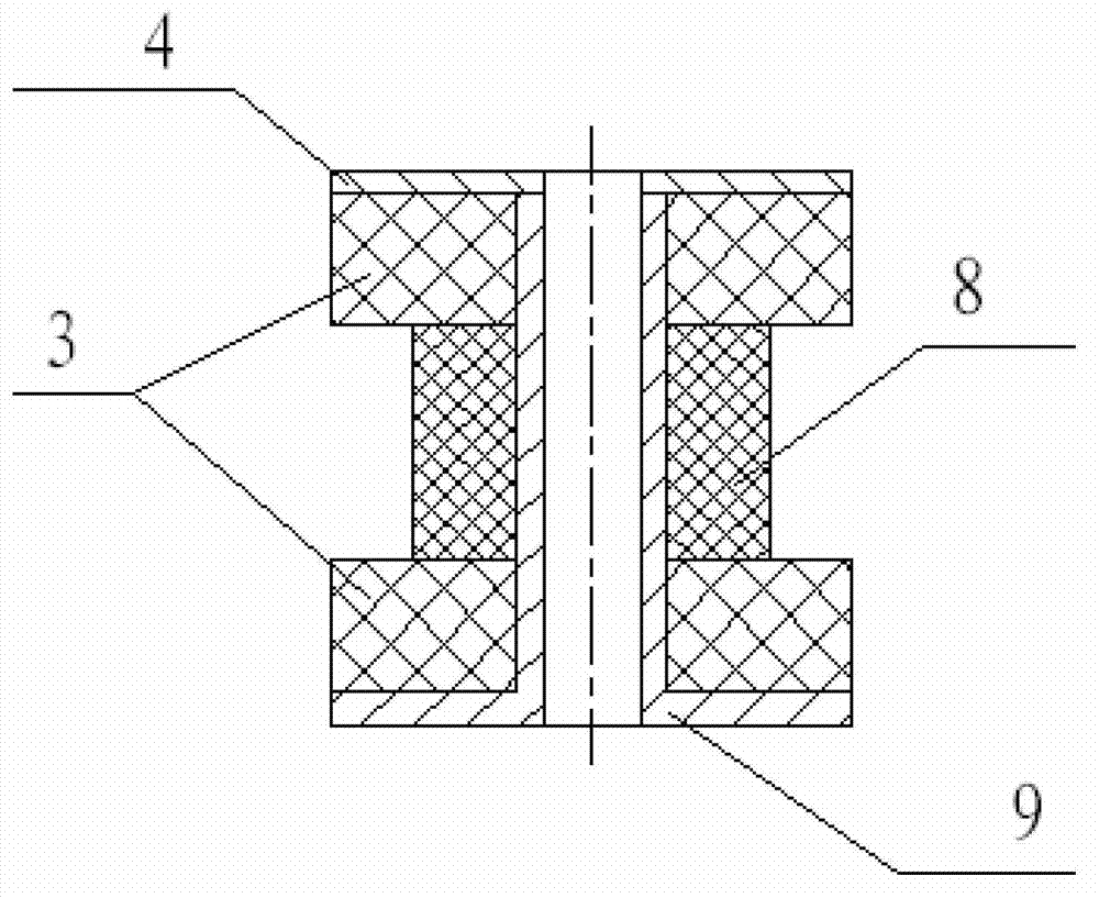
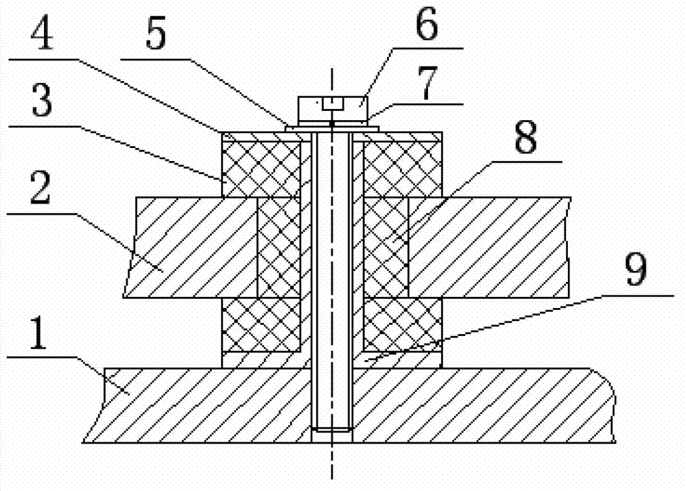
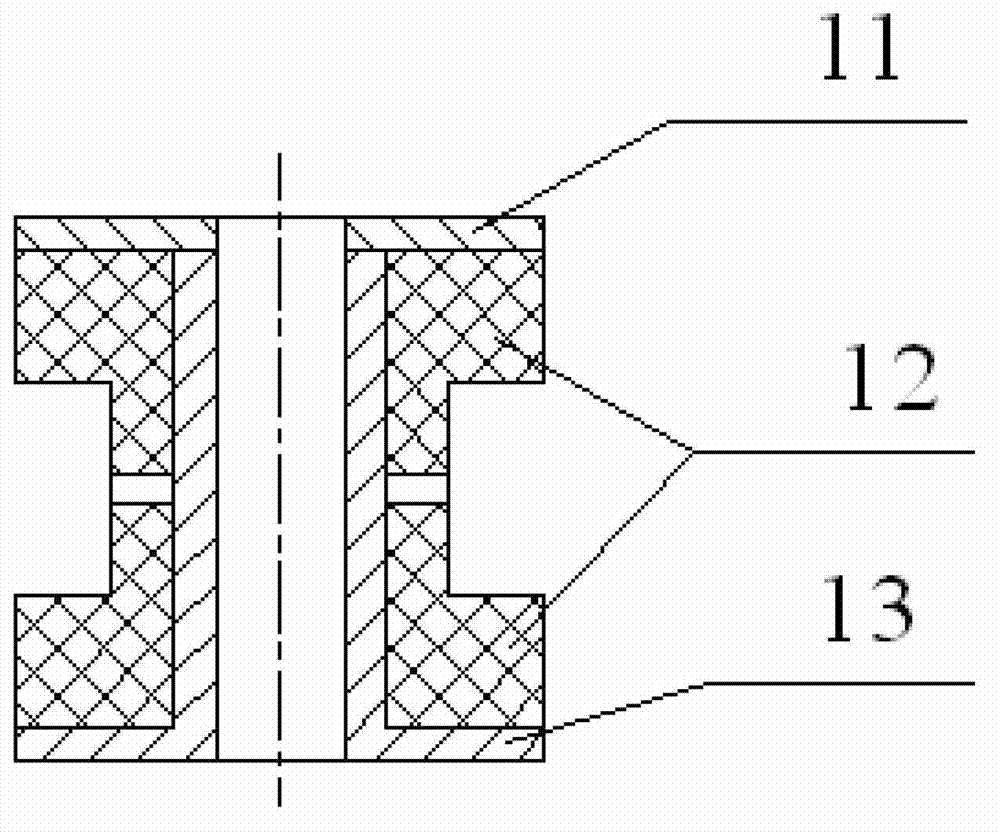
[0026] A combined rubber shock absorber, such as figure 1 As shown, it includes rubber damping pad 3, rubber damping column 8, metal limit bushing 9 and metal limit washer 4;

[0027] The cross section of the metal limit bushing 9 is an inverted "T" shape, the upper part is a hollow cylinder, and the lower part is a ring;

[0028] The top and the bottom of the metal limit bushing 9 are rubber damping pads 3, and the rubber damping pads 3 are set on the cylinder of the metal limit bushing 9;

[0029] The middle part of the metal limit bushing 9 is a rubber damping column 8, and the rubber damping column 8 is set on the cylinder of the metal limit bushing 9;

[0030] The rubber damping pad 3 is in contact with the rubber damping column 8;

[0031] The metal spacer 4 is screwed to the top end of the metal spacer bushing 9 .

[0032] The rubber damping pad 3 is made of damping material ZN-35, and its size is: inner diameter 10mm, outer diameter 24mm, height 6mm;

[0033] The ...

Embodiment 2

[0045] A combined rubber shock absorber, comprising a rubber shock absorber 3, a rubber shock absorber column 8, a metal spacer bushing 9 and a metal spacer 4;

[0046] The cross section of the metal limit bushing 9 is an inverted "T" shape, the upper part is a hollow cylinder, and the lower part is a ring;

[0047] The top and the bottom of the metal limit bushing 9 are rubber damping pads 3, and the rubber damping pads 3 are set on the cylinder of the metal limit bushing 9;

[0048] The middle part of the metal limit bushing 9 is a rubber damping column 8, and the rubber damping column 8 is set on the cylinder of the metal limit bushing 9;

[0049] The rubber damping pad 3 is in contact with the rubber damping column 8;

[0050] The metal spacer 4 is screwed to the top end of the metal spacer bushing 9 .

[0051] The rubber damping pad 3h and the rubber damping column 8 are made of damping material 35, and the size is: inner diameter 11mm, outer diameter 29mm, height 13mm; ...

Embodiment 3

[0062] A combined rubber shock absorber, comprising a rubber shock absorber 3, a rubber shock absorber column 8, a metal spacer bushing 9 and a metal spacer 4;

[0063] The cross section of the metal limit bushing 9 is an inverted "T" shape, the upper part is a hollow cylinder, and the lower part is a ring;

[0064] The top and the bottom of the metal limit bushing 9 are rubber damping pads 3, and the rubber damping pads 3 are set on the cylinder of the metal limit bushing 9;

[0065] The middle part of the metal limit bushing 9 is a rubber damping column 8, and the rubber damping column 8 is set on the cylinder of the metal limit bushing 9;

[0066] The rubber damping pad 3 is in contact with the rubber damping column 8;

[0067] The metal spacer 4 is screwed to the top end of the metal spacer bushing 9 .

[0068] The rubber damping pad 3h and the rubber damping column 8 are made of damping material ZN-37, and the dimensions are: inner diameter 7mm, outer diameter 17mm, hei...


PUM


Abstract

The invention relates to a combined type rubber shock absorber and belongs to the technical field of rubber vibration isolators. The combined type rubber shock absorber is mainly used for vibration and buffering processing of electronic equipment or instruments. The combined type rubber shock absorber comprises a rubber anti-vibration pad, a rubber anti-vibration column, a metal limiting lining and a metal limiting gasket. According to the combined type rubber shock absorber, vibration and impact energy is translated into heat energy and deformation energy of rubber materials through the deformation of rubber parts by means of a combined shock absorber structure, the rubber anti-vibration pad is capable of reducing dynamic energy of an instrument with vibration to be isolated in the axial direction, the rubber anti-vibration column is capable of reducing dynamic energy of the instrument with the vibration to be isolated in the radial direction, the metal limiting lining and the metal limiting gasket are used in a matching mode, dynamic displacement of the shock absorber is limited due to the fact that the shock absorber is installed on a base plate of the instrument through bolts, and then an installation function and a limiting function are achieved.

Description

technical field [0001] The invention relates to a combined rubber vibration absorber, which belongs to the technical field of rubber vibration isolators and is mainly used for vibration isolation and buffering treatment of electronic equipment or instruments. Background technique [0002] Because of its simple manufacturing process, convenient and effective use, and a certain buffering effect, rubber isolators have been widely used. The typical structural forms of rubber shock absorbers for electronic equipment include T-shaped shock absorber structure and metal rubber Composite shock absorber structure, etc., such as image 3 and Figure 4 shown. [0003] Although the traditional T-shaped rubber shock absorber structure has the functions of vibration isolation and buffering, it is difficult to design its axial and lateral stiffness to three-way equal frequency when the equipment installation space and interface size are limited, and the designability is not good. Strong, ...

Claims


Application Information

Patent Timeline
Patent Type & Authority Applications(China)
IPC IPC(8): F16F3/087F16F3/093
Inventor 王建月黄加才王帮武赵云峰李晓颜许捷张强赵川
Owner AEROSPACE RES INST OF MATERIAL & PROCESSING TECH
Why Eureka
Try Eureka