Spinning defective cloth detection camera and detection system thereof

A detection system and camera technology, applied in the direction of electrical testing/monitoring, etc., can solve the problems of long data transmission distance, easy to be interfered, complex installation, low detection accuracy of infrared scanning mode, etc., to facilitate wiring installation and later maintenance, and reduce system cost. cost, the effect of improving recognition accuracy and production efficiency

Inactive Publication Date: 2013-05-22
福州科迪电子技术有限公司
View PDF7 Cites 13 Cited by
  • Summary
  • Abstract
  • Description
  • Claims
  • Application Information

AI Technical Summary

Problems solved by technology

[0005] The early methods have the following shortcomings: the laser mode cannot detect the flaws caused by missing pins and missing combs, and the infrared scanning mode has low detection accuracy. They all have the disadvantages of high power consumption and complicated installation.
The recent detection method uses several general-purpose cameras or industrial digital cameras, and then transmits the data of the cameras to the same host, and the host performs data analysis and judgment, so there are problems such as huge system, high cost, and complicated wiring. , and because digital cameras need more than one million pixels, there are problems such as large amount of transmitted data, long data transmission distance, susceptible to interference and time lag

Method used


Image

  • Spinning defective cloth detection camera and detection system thereof
  • Spinning defective cloth detection camera and detection system thereof

Examples


Embodiment Construction

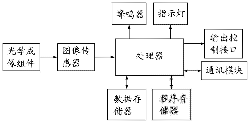
[0013] see figure 1 As shown, a textile defect detection camera of the present invention includes an optical imaging component, an image sensor, a processor, a data memory, a program memory, a communication module, a buzzer and an output control interface; the optical imaging component and the image sensor connection; the image sensor, data storage, program storage, communication module, buzzer, and output control interface are all connected to the processor; the optical imaging component images the textile cloth on the image sensor, and the image sensor converts the optical The image signal is converted into electrical information and communicated with the processor. The processor stores the electrical information in a data memory, and the program memory stores intelligent algorithms, including: wavelet filtering, neural network algorithms, and Canny (edge). detection) algorithm; the processor invokes an intelligent algorithm to analyze the electrical information in the data ...


PUM


Abstract

The invention provides a spinning defective cloth detection camera which comprises an optical imaging assembly, an imaging sensor, a processor, a data storage device, a program storage device, a communication module, a buzzer and an output control interface. The optical imaging assembly is connected with the imaging sensor. The imaging sensor, the data storage device, the program storage device, the communication module, the buzzer and the output control interface are respectively connected with the processor. The camera is used for quality decision in an online testing process, an alarm process, a control process and a finished product inspection process of continuous production processes of textile industry. Different from an industrial camera and a general camera, the spinning defective cloth detection camera is reliable in detection and simple in installation. Further provided is a detection system of the spinning defective cloth detection camera. According to the facts that the defective cloth detection function is contained in the camera and image recognition technology and intelligent algorithm of the image recognition technology are matched, the spinning defective cloth detection camera effectively improves defective cloth recognition accuracy and production efficiency.

Description

technical field [0001] The invention relates to the technical field of textile automatic control, in particular to a textile defective cloth detection camera and a detection system with the camera. Background technique [0002] In the textile defect detection system, the following two methods are generally used in the early stage: 1. Laser mode, using the principle of laser beaming, install laser transmitters and receivers at both ends of the warp knitting machine. The thread will block the beam of the laser, causing the receiving end to receive a reduction in the amount of laser light received, thereby detecting the yarn breakage event and drawing the conclusion that a defective cloth will be produced. 2. Infrared scanning mode, using the principle of infrared reflection, the detection head with infrared emission and receiver is installed on the guide rail that can move left and right, the infrared emission head emits infrared light, and the receiver detects the amount of i...

Claims


Application Information

Patent Timeline
Patent Type & Authority Applications(China)
IPC IPC(8): G05B23/02
Inventor 郑崇苏温泳荣徐平
Owner 福州科迪电子技术有限公司
Why Eureka
Try Eureka