
Harmonic suppressor

A harmonic suppressor and cavity technology, applied in waveguide devices, electrical components, circuits, etc., can solve the problems of limited depth of stop band suppression, low power capacity of suspended strip line harmonic suppressors, and inability to fine-tune, etc. Achieve the effect of high passband cut-off frequency, simple structure and convenient debugging

Active Publication Date: 2013-05-22
成都赛纳赛德科技有限公司
View PDF8 Cites 1 Cited by
  • Summary
  • Abstract
  • Description
  • Claims
  • Application Information

AI Technical Summary

Problems solved by technology

However, the suspended stripline harmonic suppressor still has disadvantages such as low power capacity, limited depth of stopband suppression, and inability to fine tune.

Method used


Image

  • Harmonic suppressor
  • Harmonic suppressor
  • Harmonic suppressor

Examples


Embodiment 1

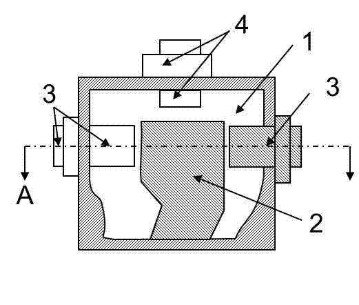
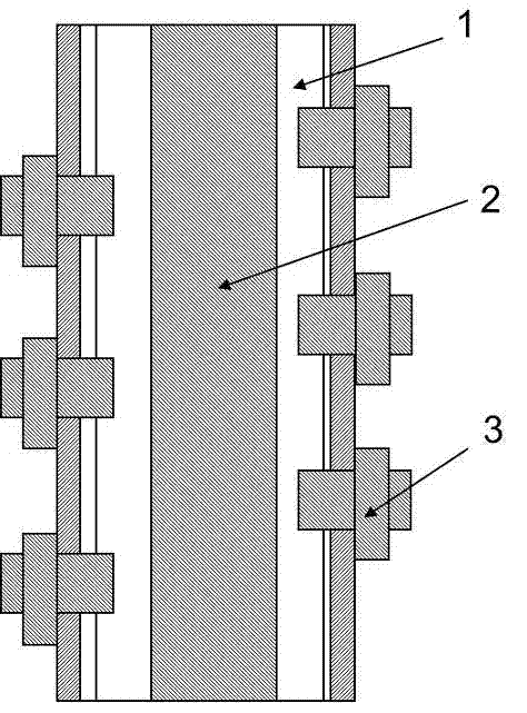
[0037] As it is figure 1 , 2 As shown, a harmonic suppressor includes a metal cavity 1, an inner conductor 2 and at least three frequency-modulating metal columns 3, the metal cavity 1 is a columnar cavity structure placed horizontally, and the axis of the metal cavity 1 is in line with the horizontal line Parallel, the inner conductor 2 is a columnar structure placed horizontally, the inner conductor 2 is arranged inside the metal cavity 1, and the bottom surface of the inner conductor 2 is connected to the bottom inner wall of the metal cavity 1; 1 is inserted into the metal cavity 1.

[0038] In order to generate a transmission zero point in the stop band of the harmonic suppressor to improve the stop band suppression steepness of the low-pass filter, the frequency-modulating metal posts 3 are alternately arranged on the left and right sides of the inner conductor 2 along the axial direction of the inner conductor 2, The depth at which the frequency-modulating metal post ...

Embodiment 2

[0048] Such as image 3 with 4 As shown, the difference between this implementation example and the first implementation example is that: the cross-sectional shape of the inner conductor 2 is rectangular, and the shape of the axis of the metal cavity 1 and the inner conductor 2 is U-shaped, and the positive shape of the inner conductor 2 is There is no matching metal post 4 inserted above.

Embodiment 3

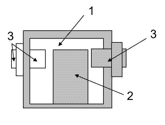
[0050] Such as figure 2 with 5 As shown, the difference between this implementation example and the first implementation example is that the cross-sectional shape of the inner conductor 2 is T-shaped.


PUM


Abstract

The invention discloses a harmonic suppressor which comprises a hollow metal cavity and an inner conductor, wherein the inner conductor is connected with an inner wall of the hollow metal cavity in the bottom. The inner conductor is inserted into the hollow metal cavity from an outer portion of the hollow metal cavity. Frequency modulation metal pillars thereof are alternately distributed on two sides of the inner conductor. Matched metal pillars are inserted into the hollow metal cavity from the right above of the inner conductor, and the metal pillars are in a certain distance to the inner conductor. The harmonic suppressor is simple in structure, easy to manufacture and assemble, convenient to debug, high in pass band cut-off frequency and abrupt in transition frequency band suppression. The harmonic suppressor is expected to be widely applied in electronic systems of various microwave wave bands, especially in the military fields of radars, missile guidance, communications and the like and the field of civilian use.

Description

technical field [0001] The invention relates to a harmonic suppressor, in particular to a harmonic suppressor composed of a ridge waveguide and a metal post, which can also be called a band-stop filter, a low-pass filter, or a trap. Background technique [0002] Suppressing spurious passbands in filter technology has always been a hot spot in the industry. Traditional methods for suppressing spurious passbands include using low-pass filters, using coaxial resonant cavities, and the like. The most common low-pass filter structures include disk-loaded coaxial inner conductors and microstrip inner conductors with abrupt impedance changes. The former has disadvantages such as complex structure, high processing precision requirements, difficult support, not steep transition frequency band suppression, and difficult debugging. The latter has the disadvantages of high loss at the high end of the channel, low power capacity, limited depth of stop band suppression, not steep enough...

Claims


Application Information

Patent Timeline
IPC IPC(8): H01P1/207
Inventor 王清源谭宜成莫坤山
Owner 成都赛纳赛德科技有限公司
Learn More