Compensation device and method of numerical control cam shaft grinding machine grinding deformation

A technology of deformation compensation device and camshaft, which is applied in the direction of abrasive belt grinders, grinding machine parts, grinding/polishing equipment, etc., can solve problems affecting work efficiency, improve machining accuracy, improve air intake and exhaust performance or Injection performance, deformation prevention effect

Active Publication Date: 2015-05-20
BEIJING UNIV OF TECH
View PDF6 Cites 1 Cited by
  • Summary
  • Abstract
  • Description
  • Claims
  • Application Information

AI Technical Summary

Problems solved by technology

[0006] At present, the commonly used method to deal with the grinding deformation of the camshaft is to add a support at the bottom of the camshaft. The upper part of the support is an arc-shaped opening, and the arc-shaped opening matches the camshaft bearing installation. However, this support can only offset the cam shaft When the shaft is under force in the lower left direction, and the diameter of the camshaft bearing installation changes, a new support must be replaced, which affects work efficiency

Method used


Image

  • Compensation device and method of numerical control cam shaft grinding machine grinding deformation
  • Compensation device and method of numerical control cam shaft grinding machine grinding deformation
  • Compensation device and method of numerical control cam shaft grinding machine grinding deformation

Examples


Embodiment Construction

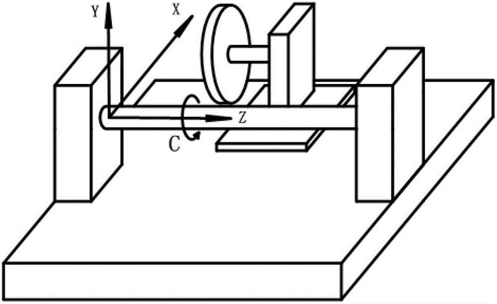
[0032] The present invention will be further described below in conjunction with the accompanying drawings.

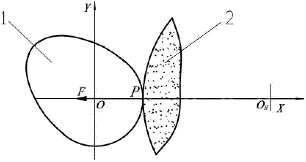
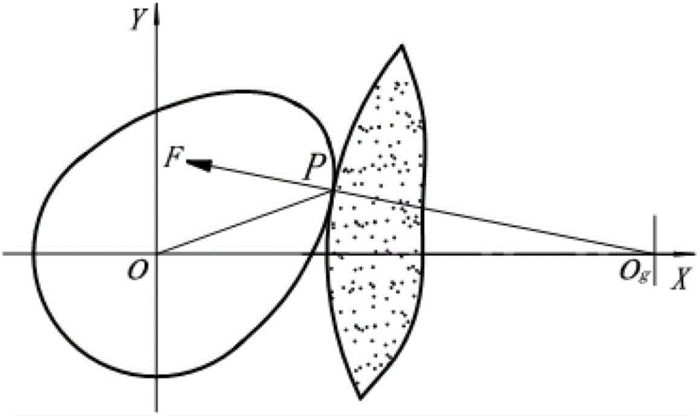
[0033] figure 2 It is the force analysis diagram of the grinding point at the base circle during CNC camshaft grinding. This figure mainly shows that when the grinding point is at the cam base circle, the camshaft will bend to the left; image 3 It is the force analysis diagram when the grinding point is on the upper half of the grinding wheel during CNC camshaft grinding. This figure mainly shows that when the grinding point is on the upper half of the grinding wheel, the camshaft will deform in the upper left direction; Figure 4It is the force analysis diagram when the grinding point is in the lower half of the grinding wheel during CNC camshaft grinding. This figure mainly shows that when the grinding point is in the lower half of the grinding wheel, the camshaft will be deformed in the downward direction to the left;

[0034] comprehensive figure 2 , image 3...


PUM


Abstract

The invention provides a compensation device and a method of numerical control cam shaft grinding machine grinding deformation. Two compensation device bases are arranged in the direction paralleled with the axial line direction of a cam shaft main shaft on one side of a cam shaft grinding machine, the bases are arranged on two guide rails, and capable of moving along the guide rails and being fastened on the guide rails through locking screws. The compensation device is arranged on the bases and composed of a servo motor, a lead screw, a nut, a connection rod, a sliding block, a roller, a control system and the like. After a cam shaft blank is clamped on a main shaft, the compensation device bases are adjusted to the position where the cam shaft is provided with a bearing and locked tightly, the diameter of the position where the cam shaft is provided with the bearing is input into the control system of the compensation device, a starting button is pressed, and then the motor of the compensation device drives the sliding block to clamp the cam shaft tightly. The compensation device and the method of numerical control cam shaft grinding machine grinding deformation have the advantages that deformation of the cam shaft because of grinding force can be compensated conveniently and machining accuracy of the cam shaft can be improved under the precondition that normal functions of the numerical control cam shaft grinding machine are not affected.

Description

technical field [0001] The invention relates to a grinding deformation compensating device for a numerically controlled camshaft grinder that supports a camshaft in three directions to counteract grinding deformation. The device includes a mechanical mechanism, an electrical control system and a control method. The invention belongs to the fields of precision machining technology and industrial automation control. Background technique [0002] Camshafts are widely used in automobile engines and diesel engines to control the intake, exhaust and fuel injection of the engine. Due to the high engine speed, the accuracy of the camshaft has a great influence on the intake and exhaust performance of the engine, the fuel injection performance and the overall performance of the machine. The performance hit is huge. [0003] The camshaft is usually cast out of the camshaft blank first, then the blank is turned, and finally sent to the CNC camshaft grinder for grinding. Grinding is th...

Claims


Application Information

Patent Timeline
Patent Type & Authority Patents(China)
IPC IPC(8): B24B19/12B24B49/16
Inventor 范晋伟刘勇军陈东菊李云谭福涛王志远
Owner BEIJING UNIV OF TECH
Why Eureka
Try Eureka