Gasification combustor of solid fuel cooking range

A solid fuel and burner technology, which is applied in the field of gasification burners, can solve the problems of short sustainable combustion time, slow ignition and ignition of cold furnaces, and high fuel requirements, so as to improve the heat radiation effect, prolong the combustion time, and strengthen the combustion. effect of the process

Active Publication Date: 2013-05-29
陕西华能恒大科技有限公司 +1
View PDF8 Cites 6 Cited by
  • Summary
  • Abstract
  • Description
  • Claims
  • Application Information

AI Technical Summary

Problems solved by technology

[0002] At present, due to the shortage of non-renewable energy sources and the rise of energy prices, more and more biomass resources need to be developed and utilized. Most of the existing gasification burners used on various stoves use a single fuel, and most of them are Non-renewable energy sources or high fuel requirements all have insufficient oxygen supply, uneven air intake, unstable and insufficient combustion, large smoke and dust, slow ignition of cold furnaces, short sustainable combustion time, and slow heat exchange speed. The problem of low thermal efficiency, and there is no fire sealing device on the burner, especially when using biomass solid fuel, the fire cannot be sealed. Every time it is used, the fire needs to be re-ignited, which is time-consuming and troublesome. Although the fire can be sealed when using coal, But in the process of sealing the fire, coal is still being consumed continuously, which wastes energy and pollutes the environment

Method used


Image

  • Gasification combustor of solid fuel cooking range
  • Gasification combustor of solid fuel cooking range
  • Gasification combustor of solid fuel cooking range

Examples


Embodiment 1

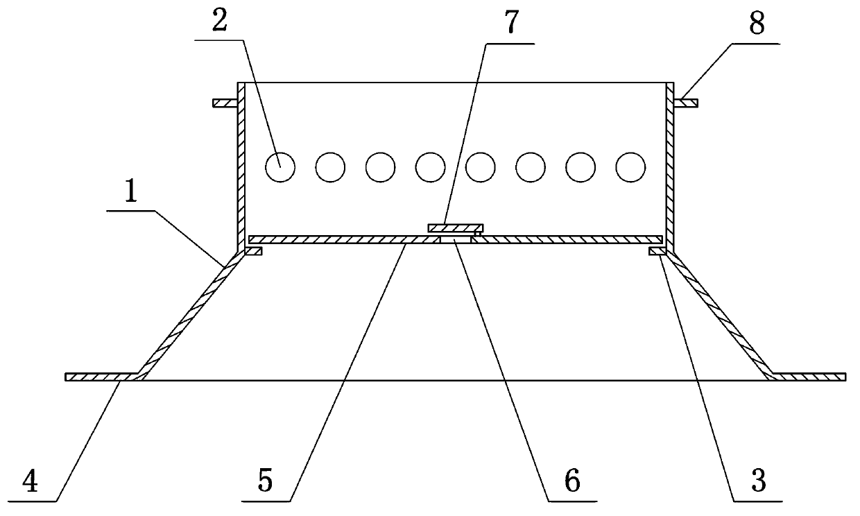
[0027] as attached figure 1 As shown, the gasification burner of the solid fuel stove in this embodiment includes a first core body 1 and a movable fire sealing cover 5; the upper part of the first core body 1 is provided with a plurality of first air inlet gasification combustion-supporting holes 2, and the first air inlet gas The combustion-supporting hole 2 is arranged above the movable fire sealing cover 5, and the inner wall of the first core body 1 is provided with a fire sealing cover baffle plate 3, and the fire sealing cover baffle plate 3 is used to support the movable fire sealing cover 5 and the fire sealing cover 5 when sealing the fire. When the fuel burns, it increases the turbulence of the flame and flue gas and air in the furnace core 18 of the stove, further mixes the combustible flue gas with the air, and prolongs the combustion of combustible flue gas and carbon particles in the flue gas. The residence time in the stove is conducive to heat exchange, prolon...

Embodiment 2

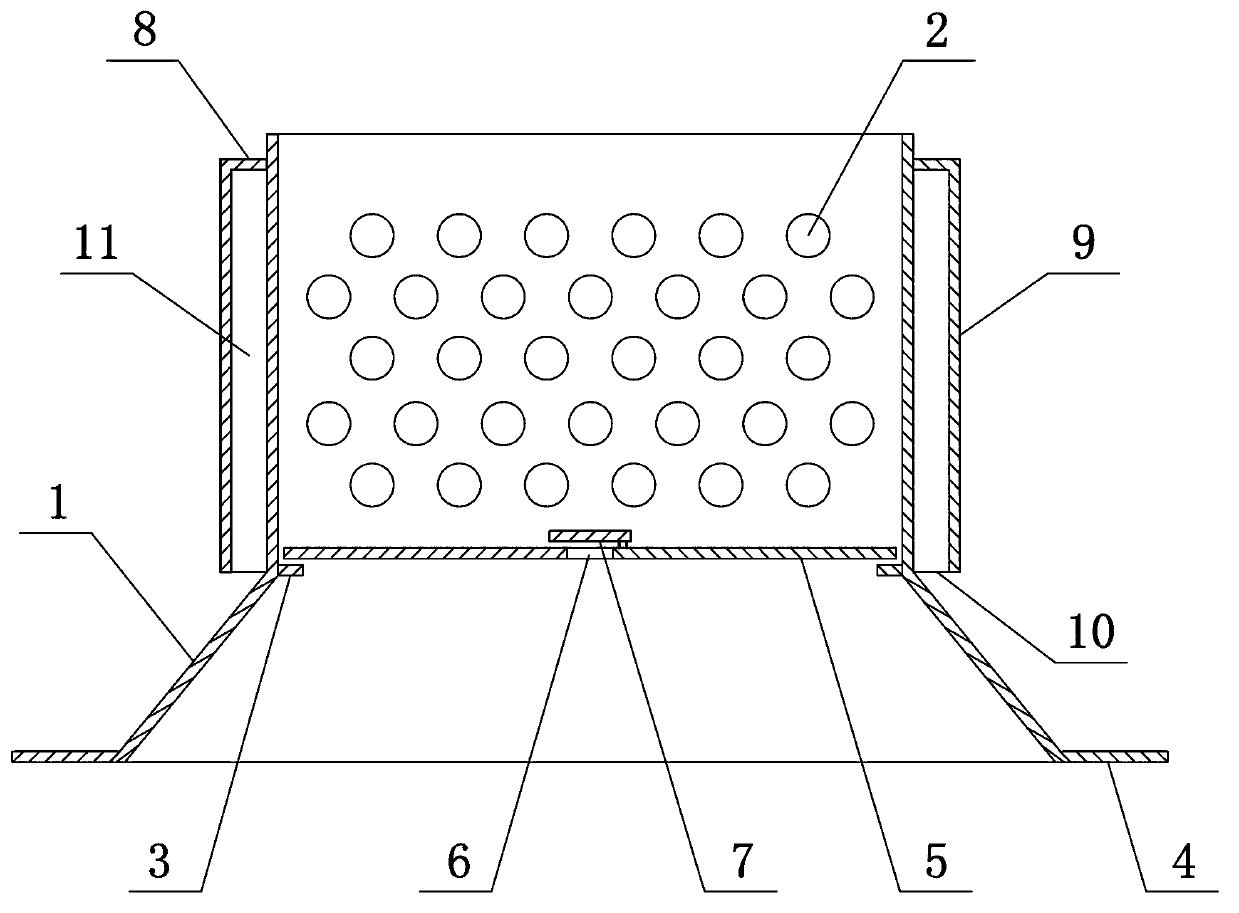
[0030] as attached figure 2As shown, the difference between the gasification burner of the solid fuel stove in this embodiment and the first embodiment is that an outer cover 9 is arranged around the upper part of the first core 1 . A burner air inlet 10 is set between the lower end of the outer cover 9 and the first core 1, the upper end of the outer cover 9 is sealed with the first core 1, and the gap between the outer cover 9 and the first core 1 is a jacket structure. , Between the outer cover 9 and the first core 1 is a burner air intake channel 11 . The top edge of the outer cover 9 and the lower edge of the first core 1 have edges extending outward. When the present embodiment is in use, it is placed on the stove core 18 of the stove just in time to form a sealed structure with the stove body and the stove core 18 (such as Figure 6 shown), on the first core 1 there are multiple rows of first air intake gasification combustion-supporting holes 2 arranged along the ci...

Embodiment 3

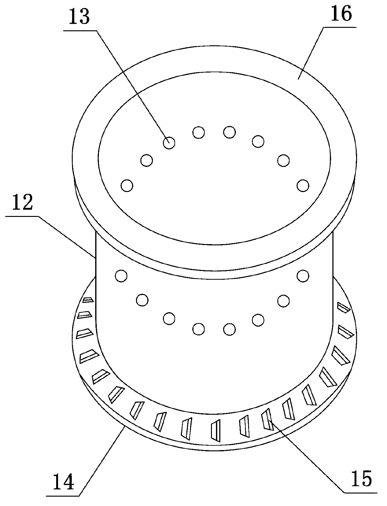
[0032] as attached image 3 , 4 As shown, the gasification burner of the solid fuel stove in this embodiment is provided with a movable cyclone combustion supporter in the first core 1, and the upper and lower parts of the cyclone combustion supporter are provided with butt joints with the first core body 1 of the burner. The sealed second core 12 has a bottom wall 14 and a top wall 16 .

[0033] The upper and lower ends of the cyclone burner are through structures, and its shape can be a cylinder, a cone, an ellipsoid or a square. This embodiment is a cylinder, and the bottom wall 14 of the second core 12 is provided with a plurality of Or circular third air intake gasification combustion-supporting hole 15, the third air intake gasification combustion-supporting hole 15 is an oblique hole with the same oblique direction, and a plurality of second air intake gasification combustion-supporting holes arranged along the circumference of the side wall of the second core body 12 ...


PUM


Abstract

The invention provides a gasification combustor of a solid fuel cooking range which comprises a first core body and a movable whirlwind combustion-supporting device. A plurality of air-in and gasification combustion-supporting holes are arranged on the first core body, a fire-sealing cover baffle plate is arranged on the inner wall of the first core body, and when an air blower is used for compulsorily supporting air for combustion supporting, the movable whirlwind combustion-supporting device is arranged on the fire-sealing cover baffle plate in the first core body. The movable whirlwind combustion-supporting device comprises a second core body, a top wall and a bottom wall, wherein the top wall is arranged on the upper portion of the second core body, and the bottom wall is arranged on the lower portion of the second core body. A plurality of second air-in and gasification combustion-supporting holes are arranged on the periphery of the second core body, and the bottom wall of the second core body is provided with a plurality of third air-in and gasification combustion-supporting holes which are coincident in slant directions. A cold furnace is easy to fire up and fast to inflame; flame rotates for combustion; and heat power is strong. The gasification combustor saves energy and is environment-friendly; and when fire is sealed, the movable whirlwind combustion-supporting holes are taken out, and the movable fire-sealing cover is arranged on the fire-sealing cover baffle plate to seal the fire. The gasification combustor is applicable to a boiler or a hot blast stove with solid fuel combusted, and use of combustion equipment with any structure such as the cooking range in a matched mode.

Description

technical field [0001] The invention relates to the technical field of gasification burners, in particular to a gasification burner used on solid fuel stoves capable of burning coal and biomass. Background technique [0002] At present, due to the shortage of non-renewable energy sources and the rise in energy prices, more and more biomass resources need to be developed and utilized. Most of the existing gasification burners used on various stoves use a single fuel, and most of them are Non-renewable energy sources or high fuel requirements all have insufficient oxygen supply, uneven air intake, unstable and insufficient combustion, large smoke and dust, slow ignition of cold furnaces, short sustainable combustion time, and slow heat exchange speed. The problem of low thermal efficiency, and there is no fire sealing device on the burner, especially when using biomass solid fuel, the fire cannot be sealed. Every time it is used, the fire needs to be re-ignited, which is time-...

Claims


Application Information

Patent Timeline
Patent Type & Authority Applications(China)
IPC IPC(8): F23B90/06
Inventor 叶绍国刘金雪
Owner 陕西华能恒大科技有限公司
Why Eureka
Try Eureka