
Integrated type energy-saving shuttle kiln

A technology of conjoined type and shuttle type kiln, which can be used in furnace types, waste heat treatment, furnaces, etc., can solve the problems of secondary utilization, affect the heating speed of the kiln, and cannot be recycled, so as to reduce energy consumption and save energy. , the effect of improving heat utilization

Inactive Publication Date: 2013-05-29
路今铧
View PDF8 Cites 3 Cited by
  • Summary
  • Abstract
  • Description
  • Claims
  • Application Information

AI Technical Summary

Problems solved by technology

This has a certain effect on energy saving, but at the same time it brings another problem. Part of the heat energy in the furnace is taken away, which affects the heating rate of the kiln, and all the waste heat of the tail fire gas in the high-temperature kiln cannot be used. Recycle for secondary use

Method used


Image

  • Integrated type energy-saving shuttle kiln
  • Integrated type energy-saving shuttle kiln
  • Integrated type energy-saving shuttle kiln

Examples


Embodiment 1

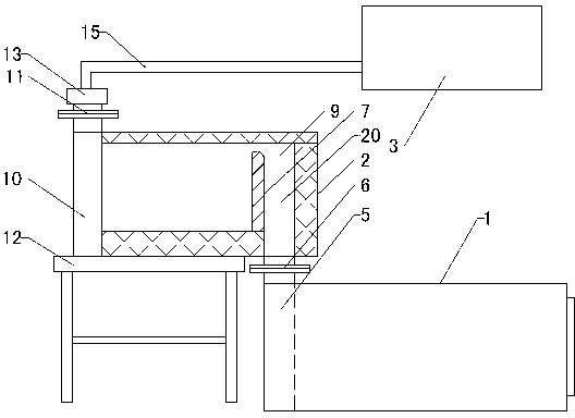
[0026] Refer to attached figure 1 : One-piece energy-saving shuttle kiln, including high-temperature kiln 1, high-temperature kiln flue 5 on one side of high-temperature kiln 1, and high-temperature kiln smoke outlet shutter 6, and high-temperature kiln smoke outlet shutter 6 is installed on The smoke outlet of the high-temperature kiln flue 5 is used to control the atmosphere in the high-temperature kiln 1. The high-temperature kiln flue 5 is vertically arranged on the inner side of the high-temperature kiln 1, and an installation is arranged on the outer side of the high-temperature kiln 1. Frame 12, the medium temperature furnace 2 is installed on the top side of the high temperature furnace 1 through the mounting frame 12, and the smoke inlet 18 of the medium temperature furnace 2 is connected with the high temperature furnace smoke outlet ram at the smoke outlet of the high temperature furnace flue 5 6. The volume of the medium-temperature kiln 2 is less than or equal to ...

Embodiment 2

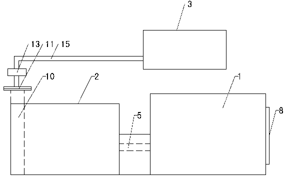
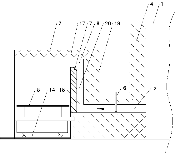
[0029] Refer to attached figure 2 and 3 : The high-temperature kiln flue 5 is horizontally arranged at the middle and lower part of one side of the high-temperature kiln 1, the high-temperature kiln 1 is horizontally connected to the medium-temperature kiln 2 through the high-temperature kiln flue 5, and the middle part of the high-temperature kiln flue 5 is vertically arranged The high-temperature kiln smoke outlet ram 6 can also be provided with a kiln car 8 and a track 14 matched with the kiln car 8 in the medium-temperature kiln 2 . Other settings are the same as in Example 1.

Embodiment 3

[0031] Refer to attached Figure 4 The high-temperature kiln flue 5 is vertically arranged on one side of the high-temperature kiln 1, and the medium-temperature kiln 2 is installed on the top surface of the high-temperature kiln 1, and the bottom of the medium-temperature kiln 2 communicates with the high-temperature kiln flue 5. Other settings are the same as in Example 1.

[0032] The working process is as follows: when the present invention is working, first, high-temperature firing and molding of ceramic products are carried out in the high-temperature kiln 1, and the high-temperature pyrotechnic gas generated by the high-temperature kiln 1 enters the smoke inlet of the medium-temperature kiln 2 through the high-temperature kiln flue 5 18, and then pass through the flue inlet 20 formed between the fire-retaining wall 7 and the back wall 19 of the medium-temperature kiln, and the gap between the top of the fire-retaining wall 7 and the top of the medium-temperature kiln 2 fo...


PUM


Abstract

The invention discloses an integrated type energy-saving shuttle kiln, belongs to the field of shuttle kiln equipment, and particularly relates to the integrated type energy-saving shuttle kiln of secondary recycling tail pyrotechnic gas and obvious energy-saving effect. The integrated type energy-saving shuttle kiln comprises a high temperature kiln (1), a high temperature kiln chimney flue (5) and a chimney flue stack nozzle flashboard (6), wherein the high temperature kiln chimney flue (5) and the chimney flue stack nozzle flashboard (6) are both arranged on one side of the high temperature kiln (1). The integrated type energy-saving shuttle kiln is characterized in that the stack nozzle of the high temperature kiln chimney flue (5) is connected with an intermediate temperature kiln (2), and the high temperature kiln (1) is communicated with the intermediate temperature kiln (2) as whole. According to the structure of the integrated type energy-saving shuttle kiln, the intermediate temperature kiln of a smaller size is added to carry out recovery of the tail pyrotechnic gas of the high temperature kiln of big size and complete reutilization, the consumption of energy is obviously reduced, heat utilization efficiency is improved, and energy is saved by 60% to 70%, the number of kilns is increased and at the same time the normal temperature needs of other kilns cannot be influenced, and the problem of the pollution to the environment caused by the pyrotechnic gas can be solved well.

Description

technical field [0001] A conjoined energy-saving shuttle kiln belongs to the field of shuttle kiln equipment, and specifically relates to a conjoined shuttle kiln with secondary recovery and utilization of tail fire gas and remarkable energy-saving effect. Background technique [0002] As a non-renewable resource on the earth, energy has become a major obstacle to the development of ceramics due to the continuous increase in consumption and the doubled price. In the face of rising fuel prices, the country has formulated a number of energy-saving and emission-reduction regulations. Therefore, the task of energy saving and consumption reduction for ceramic enterprises is more urgent. According to relevant information, the fuel consumption of my country's ceramic industry currently accounts for about 35% to 45% of the total production cost. The kiln is the most critical thermal equipment for ceramic enterprises, and it is also the equipment that consumes the most energy. Due t...

Claims


Application Information

Patent Timeline
Patent Type & Authority Applications(China)
IPC IPC(8): F27B19/04F27D17/00
Inventor 路今铧路晗
Owner 路今铧
Learn More