Cable outlet system for high voltage cable oscillatory wave partial discharge detection system

A technology for partial discharge detection and high-voltage cables, which is used in the measurement of lead wires/probes, dielectric strength measurement, and measurement device casings, etc., which can solve the problems of inconvenient installation and removal, inaccurate detection results, and unstable connections. Achieve the effect of easy disassembly and assembly, favorable field test and no partial discharge

Active Publication Date: 2015-11-04
STATE GRID SHANDONG ELECTRIC POWER +1
View PDF9 Cites 0 Cited by
  • Summary
  • Abstract
  • Description
  • Claims
  • Application Information

AI Technical Summary

Problems solved by technology

[0004] The cable oscillatory wave partial discharge detection system is a form of offline detection. When the cable oscillatory wave detection system is used to detect cable partial discharge, it is generally used to connect the outgoing part of the cable with the cable oscillatory wave detection equipment through clips, screws or even welding. Some even use insulating tape to fix and realize insulation at the connection between the cable outlet part and the cable oscillation wave detection equipment. This method is very rough. It is easy to cause corona and discharge, and in severe cases, it will cause breakdown, and the fixation is not firm, the connection is unstable, it is very inconvenient to install and disassemble, and it is easy to cause unnecessary damage to the cable
Most importantly, the use of the existing connection method will lead to partial discharge in the cable outlet part due to the loose fixation between the cable outlet part and the cable oscillatory wave detection device when the cable oscillatory wave detection system is used to detect the partial discharge of the cable. , resulting in inaccurate detection results

Method used


Image

  • Cable outlet system for high voltage cable oscillatory wave partial discharge detection system
  • Cable outlet system for high voltage cable oscillatory wave partial discharge detection system
  • Cable outlet system for high voltage cable oscillatory wave partial discharge detection system

Examples


Embodiment Construction

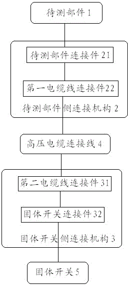
[0034] The structure of a cable outlet system for a high-voltage cable oscillatory wave partial discharge detection system according to the present invention is as follows: figure 1 As shown, it includes a connection mechanism 2 on the side of the component under test, a connection mechanism 3 on the side of the solid switch and a high-voltage cable connection 4, wherein the connection mechanism 2 on the side of the component under test includes a connection part 21 of the part under test and a first cable connection part 22 , the component to be tested connector 21 is connected to the component to be tested 1; the solid switch side connection mechanism 3 includes a solid switch connector 32 and a second cable connector 31, and the solid switch connector 32 is connected to the solid switch 5; The two ends of the high-voltage cable connecting wire 4 are respectively connected to the first cable connecting piece 22 of the connecting mechanism 2 on the part under test side and the...


PUM


Abstract

The cable wire system for high voltage cable oscillation wave partial discharge detection system comprises a side connection mechanism of units under test, a side connection mechanism of solid switches and high voltage connecting lines, wherein the side connection mechanism of units under test includes a connecting piece of units under test and a first cable connector and the connecting piece of units under test is connected with the units under test. The side connection mechanism of solid switches includes a solid switch connecting piece and a second cable connector and the solid switch connecting piece is connected with the solid switch. The two ends of high voltage connecting line are respectively connected with the first cable connector of the side connection mechanism of units under test and the second cable connector of the side connection mechanism of solid switches. The system is simple in structure. Further, the cable wire system is not easy to generate corona and to discharge through the design which the cable wire part has a large distance from cable oscillation wave testing device, so that the system is stable and reliable in connection, capable of no partial discharge and beneficial to site test.

Description

Technical field [0001] The invention involves a cable circulation structure in a 10KV oscillating wave system. It is specifically a cable qualifying system for high -voltage cable oscillation wave local discharge detection system, which belongs to the field of local discharge detection technology in cable oscillation waves. Background technique [0002] The detection methods of local discharge of cables are mainly the following: 1. Local discharge detection of cables under construction frequency voltage; 2. Local discharge detection under the ultra -low -frequency voltage; 3. Local discharge detection of cable under DC damping oscillation voltage;Due to the large capacity capacity of the power cable, it is difficult to perform local discharge detection under the construction of industrial frequency voltage at the scene; the method 2 of them 2 requires a long test time, which can cause new defects in the cable;Method 3, because XLPE (Crosslinked Polyethylene, cross -linked polyeth...

Claims


Application Information

Patent Timeline
Patent Type & Authority Patents(China)
IPC IPC(8): G01R31/12G01R1/06G01R1/04
Inventor 时翔王兴照韩克存张利群雍军杨波孙晓斌林晓礼张明财梁涛毕建鑫郭建豪何永谦
Owner STATE GRID SHANDONG ELECTRIC POWER
Why Eureka
Try Eureka