
Thin airfoil type blade of large-scale fan

A fan and thin wing technology, applied in the field of thin airfoil blades, can solve the problems of low utilization rate of wind energy and heavy structure weight, and achieve the effects of reducing fatigue load, reducing structure weight and improving wind energy utilization efficiency

Inactive Publication Date: 2013-06-05
GUODIAN UNITED POWER TECH
View PDF4 Cites 8 Cited by
  • Summary
  • Abstract
  • Description
  • Claims
  • Application Information

AI Technical Summary

Problems solved by technology

[0004] The technical problem to be solved by the present invention is to provide a thin airfoil blade of a large fan, which can reduce the weight and improve the overall performance of the fan, thereby overcoming the existing problems of heavy structure and low utilization rate of wind energy

Method used


Image

  • Thin airfoil type blade of large-scale fan
  • Thin airfoil type blade of large-scale fan
  • Thin airfoil type blade of large-scale fan

Examples


Embodiment Construction

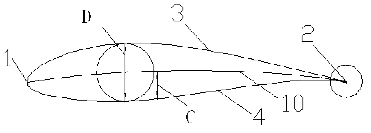
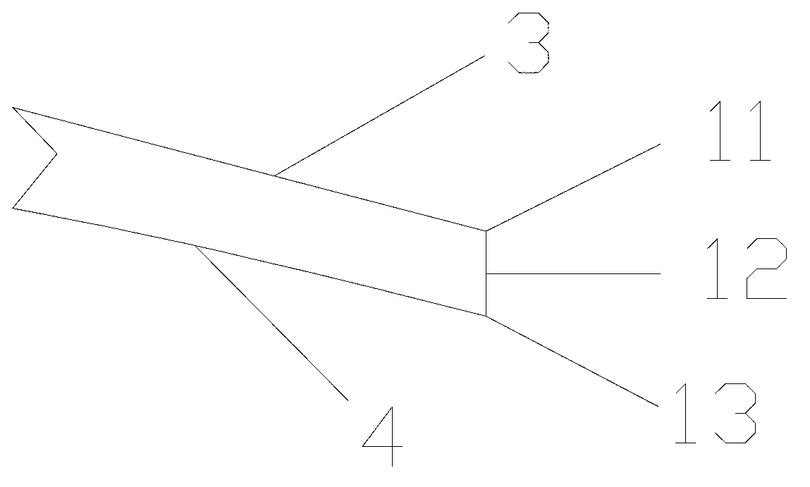
[0018] refer to figure 1 , figure 2 , the present invention provides a blade airfoil with a relative thickness of 18% (named UP18). It is formed with the profiled line 4 of the pressure surface, in which the leading edge 1 is a circular arc, and the leading edge 1 is respectively connected with the profiled line 3 of the suction surface and the profiled line 4 of the pressure surface. The curvature at the connection point is continuous, and the end 11 of the profiled line of the suction surface The ends 13 of the surface lines 4 are connected to form the trailing edge 2 .

[0019] first of all, yes figure 1 The names of the various parts are defined as follows:

[0020] 1. Middle arc 10: Make a series of inscribed circles of suction surface profile 3 and pressure surface profile 4 in the airfoil, and the line connecting the centers of these inscribed circles is called the center arc 10 of the airfoil.

[0021] 2. Chord length: the connecting line between the front and rea...


PUM


Abstract

The invention relates to a thin airfoil type blade of a large-scale fan. An outer contour of a cross-section of a blade tip part of the thin airfoil type blade of the large-scale fan comprises a leading edge, a trailing edge, a suction surface profile and a pressure profile, wherein the distance between the leading edge and the trailing edge is chord length, the thickness of an end surface of the trailing edge is 0% to 5% of the chord length, and the radius of the leading edge is 2.5% to 3.5% of the chord length. The maximum thickness of the section-cross is 17.5% to 18.5% of the chord length, the distance of a thickest portion of the cross-section and the leading edge is 25% to 35% of the chord length, the maximum bending degree of the cross-section is 3.0% to 4.0% of the chord length, and the distance of a portion with the maximum bending degree and the leading edge is 40% to 60% of the chord length. The comprehensive performance of the thin airfoil is better than the comprehensive performance of a traditional depleted uranium (DU), national advisory committee for aeronautics (NACA) airfoil with the same relative thickness, not only is the wind energy utilization rate improved, but also the structural weight is reduced and the fatigue loading is reduced. The thin airfoil type blade of the large-scale fan becomes an important technical basis for developing large-scale low-cost wind turbines.

Description

technical field [0001] The invention relates to the field of wind power generation, in particular to a thin airfoil blade of a large fan. Background technique [0002] With the increasingly prominent energy and environmental issues, the abundant, pollution-free and renewable wind energy has gradually attracted people's attention. The core component of the wind turbine—the blade has airfoil sections with different thicknesses and twist angle distributions. The aerodynamic performance of the airfoil is closely related to the operating efficiency and reliability of the whole machine. Early wind turbine blade design preferred the aeronautical airfoil with relatively mature development and better lift-drag characteristics, but practice has proved that the design of this type of airfoil cannot well meet the design and use requirements of the wind turbine, such as for stall-type wind turbines. As far as the wind turbine is concerned, excessive peak energy and peak load will be gen...

Claims


Application Information

Patent Timeline
IPC IPC(8): F03D11/00
CPCY02E10/722Y02P70/50
Inventor 周文明代海涛刘丹
Owner GUODIAN UNITED POWER TECH
Learn More