Autocorrelator

A technology of autocorrelator and optical path, applied in the direction of instruments, etc., can solve the problems of not providing calibration optical path, noise, etc., and achieve the effect of reducing the difficulty of optical path adjustment, simple optical path structure, and saving time

Inactive Publication Date: 2013-06-05
北京量子光通科技有限公司
View PDF5 Cites 12 Cited by
  • Summary
  • Abstract
  • Description
  • Claims
  • Application Information

AI Technical Summary

Problems solved by technology

[0008] The technical problem solved by the present invention is: since the beam splitter of the autocorrelator in the prior art is composed of two beam splitters with parallel sides, and none of them provides a calibration optical path, the structure of the optical path is complicated and the adjustment of

Method used


Image

  • Autocorrelator
  • Autocorrelator
  • Autocorrelator

Examples


Embodiment Construction

[0046] Specific embodiments of the present invention will be described in detail below in conjunction with the accompanying drawings.

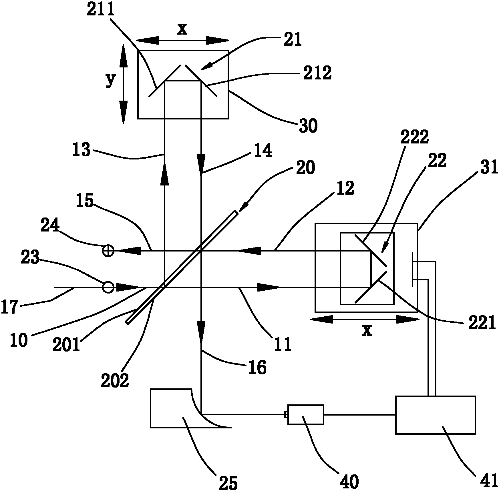
[0047] Such as figure 1 Shown, the autocorrelator of the embodiment of the present invention comprises:

[0048] The incident reference aperture 23, the measured laser light 17 incident at the same height and straightly passes through the incident reference aperture 23 to form the incident optical path 10;

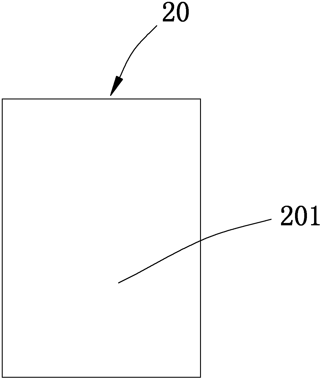
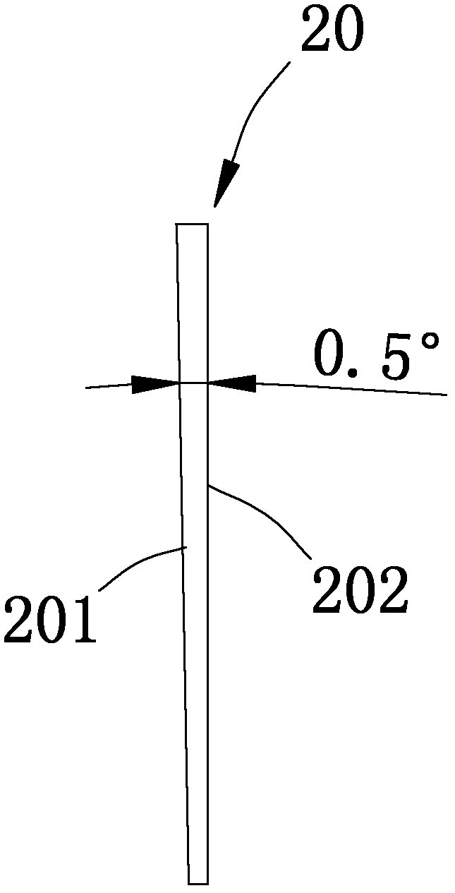
[0049] The wedge-shaped beam splitter 20 is located on the incident light path 10, and its angle with the incident light path 10 is 45°. The first light path 11 and the third light path 13 are respectively formed after the incident light path 10 is transmitted and reflected by the wedge-shaped beam splitter 20. The first light path 11 and the third optical path 13 are perpendicular to each other;

[0050]The first right-angle reflector 21 includes a first plane reflector 211 and a second plane reflector 212; the first plane reflector 211...


PUM

PropertyMeasurementUnit
Wedge angleaaaaaaaaaa

Abstract

The invention discloses an autocorrelator for measuring the width of ultra-short laser pulses. The autocorrelator comprises an incidence reference hole, a wedge-shaped spectroscope, a first right-angle reflector, a second right-angle reflector, a scanning device platform, a paraboloidal mirror, a detector and a control device, wherein the incidence reference hole is used for passing to-be-detected lasers which enter horizontally and straightly at equal heights to form an incidence light path; and the wedge-shaped spectroscope is positioned on the incidence light path, and the included angle of the wedge-shaped spectroscope and the incidence light path is 45 degrees. According to the autocorrelator, the wedge-shaped spectroscope is adopted to replace two beam splitting slices in the prior art, and the two sides of each beam slitting slice are parallel to each other, so that a light path structure of the autocorrelator is simple, and interference field signals formed by multiple reflections of two surfaces of the wedge-shaped spectroscope cannot coincide with an emergent light path any more, so that the detector can detect neat autocorrelation signals.

Description

technical field [0001] The invention relates to the technical field of laser parameter measurement, in particular to an autocorrelator for measuring ultrashort laser pulse width. Background technique [0002] With the rapid development of laser technology, the laser pulse width is continuously narrowed. In the field of ultrashort and ultrafast lasers, people have obtained femtosecond lasers with pulse widths less than 10 fs (femtoseconds) through experimental means. Ultrashort laser pulse widths Measurement is the most important problem in ultrashort laser parameter measurement. [0003] The traditional method for measuring laser pulse width is to use photoelectric two-photon detectors to directly display the pulse waveform. However, the fastest response time of existing photoelectric response devices is on the order of picoseconds, which cannot be used to measure ultra- Short laser pulse information requires femtosecond laser pulses to scan themselves, using the nonlinear ...

Claims


Application Information

Patent Timeline
IPC IPC(8): G01J11/00
Inventor 熊桂生张志刚祝传文王树雨
Owner 北京量子光通科技有限公司
Why Eureka
Try Eureka