
Convolution-based X-ray CT system beam hardening correction method

A beam hardening correction and X-ray technology, applied in the field of industrial CT system applications, can solve problems such as inconsistency of projection values, loss of image information, etc., and achieve high-precision detection and remarkable results

Inactive Publication Date: 2013-06-05
CHONGQING UNIV
View PDF7 Cites 23 Cited by
  • Summary
  • Abstract
  • Description
  • Claims
  • Application Information

AI Technical Summary

Problems solved by technology

polychromatic projection value p p It does not have a linear relationship with the thickness l of the X-ray passing through the measured object, so it can be seen that the actually obtained projection value p p and the projection value p used for reconstruction m are not the same, the inconsistency of the projection values ​​causes the presence of artifacts in the reconstructed image
[0017] Sclerosis correction has been a research hotspot in the international CT field since 1975. The current sclerosis correction method is mainly divided into two types: pre-processing method and post-processing method. The pre-processing method corrects sclerosis from the perspective of sclerosis mechanism. Fundamentally remove the cupping artifact; while the post-processing method mainly corrects from the perspective of the reconstructed CT image, the calculation is time-consuming, and part of the image information will be lost
These hardening correction methods can inhibit the hardening effect under certain conditions, but due to the limitations of CT testing equipment and non-destructive testing principles, there is no correction method that can completely suppress the hardening effect.

Method used


Image

  • Convolution-based X-ray CT system beam hardening correction method
  • Convolution-based X-ray CT system beam hardening correction method
  • Convolution-based X-ray CT system beam hardening correction method

Examples


Embodiment Construction

[0040] The preferred embodiments of the present invention will be described in detail below with reference to the accompanying drawings.

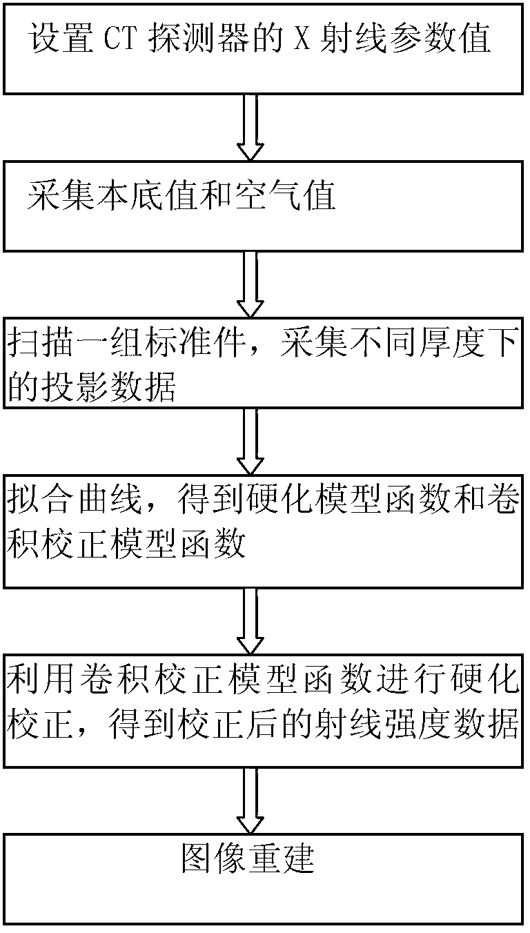
[0041] figure 1 Be beam hardening correction method flow chart of the present invention, this correction method comprises the following steps: Step 1: setting CT system scanning parameter; Step 2: do not open ray source, the background value I of acquisition system bkg ; Step 3: Turn on the ray source, scan the air under the current laboratory, and obtain the current air ray intensity I 0 ; Step 4: Utilize the X-ray CT system to scan a group of standard parts with known thickness, subtract the background value from the obtained sampling data to obtain the actual effective radiation intensity data I; substitute I into the formula p p =ln(I 0 / I), get the polychromatic projection value p under different thicknesses p ;Step 5: take the thickness l as the abscissa, the polychromatic projection value p p As the ordinate, the hardening model ...


PUM


Abstract

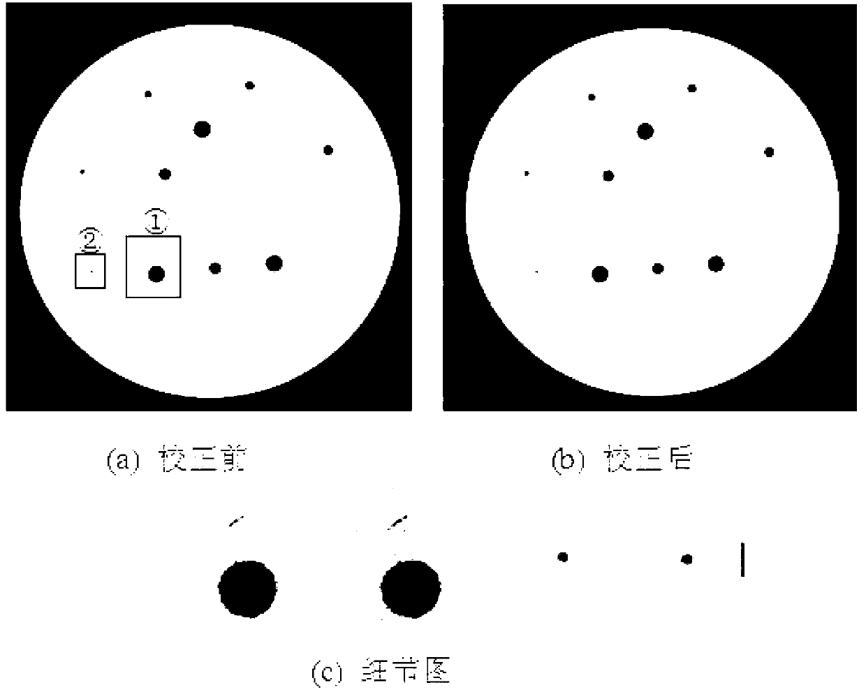
The invention discloses a convolution-based X-ray CT system beam hardening correction method, belonging to the applying field of industrial CT systems. The method comprises the following steps of: I. conducting scattering correction by clinging an aluminum foil filter plate to a rear collimator; II. setting the scanning parameter of a CT system; III. collecting the background value of the system with a ray source not opening; IV. opening the ray source, and scanning the air in the current laboratory to obtain the ray strength of the current air; V. scanning a group of standard parts, and collecting the projection data under different thicknesses; VI. fitting a curve to obtain a hardening model and a convolution correction model; VII. conducting hardening correction by utilizing the function of the convolution correction model to obtain the corrected ray strength data; and VIII. conducting image reconstruction by using the corrected ray strength data. With the correction method, the beam hardening correction effect is obvious, the edge of a detected object can be well maintained, the detail part of the detected object can be saved, and the high-precision detection need can be met.

Description

technical field [0001] The invention belongs to the application field of industrial CT systems, and relates to a beam hardening correction method of an X-ray CT system. Background technique [0002] With the rapid development and maturity of nuclear physics technology, according to the principle of the interaction between rays and matter, nuclear technology has been widely used in marginal science, industry and medicine, and the method of using rays to detect and scan objects has also emerged. , this method obtains the relevant characteristics of the material to be tested by analyzing the intensity change of the rays passing through the material to be tested. factors. [0003] In the industrial CT imaging system, CT scanning is to reconstruct the internal structure of the object by obtaining the X-ray intensity value after passing through the measured object, and then judge whether there are cracks, impurities, etc. inside the measured object. However, due to the existence...

Claims


Application Information

Patent Timeline
IPC IPC(8): G01N23/04
Inventor 高富强周钦蔡玉芳陈赟飞冯永李岭兰扬严强安康
Owner CHONGQING UNIV
Learn More