High-sensitivity optical-type airspeed measuring device

A measuring device, fiber-optic technology, which is applied in the direction of measuring fluid velocity by using differential pressure, can solve problems such as unfavorable safe flight of aircraft, and achieve the effects of high practical value, large dynamic range and low cost

Inactive Publication Date: 2013-06-05
XIAN JINHE OPTICAL TECH
View PDF0 Cites 4 Cited by
  • Summary
  • Abstract
  • Description
  • Claims
  • Application Information

AI Technical Summary

Problems solved by technology

[0004] The sensitive components of existing differential pressure airspeed gauges are mainly electronic sensing components, which are easily affected by electroma

Method used


Image

  • High-sensitivity optical-type airspeed measuring device
  • High-sensitivity optical-type airspeed measuring device
  • High-sensitivity optical-type airspeed measuring device

Examples


Embodiment 1

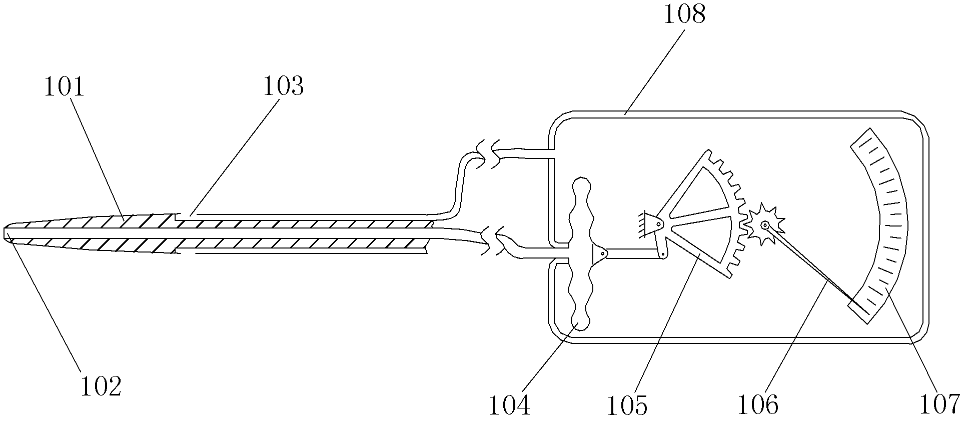
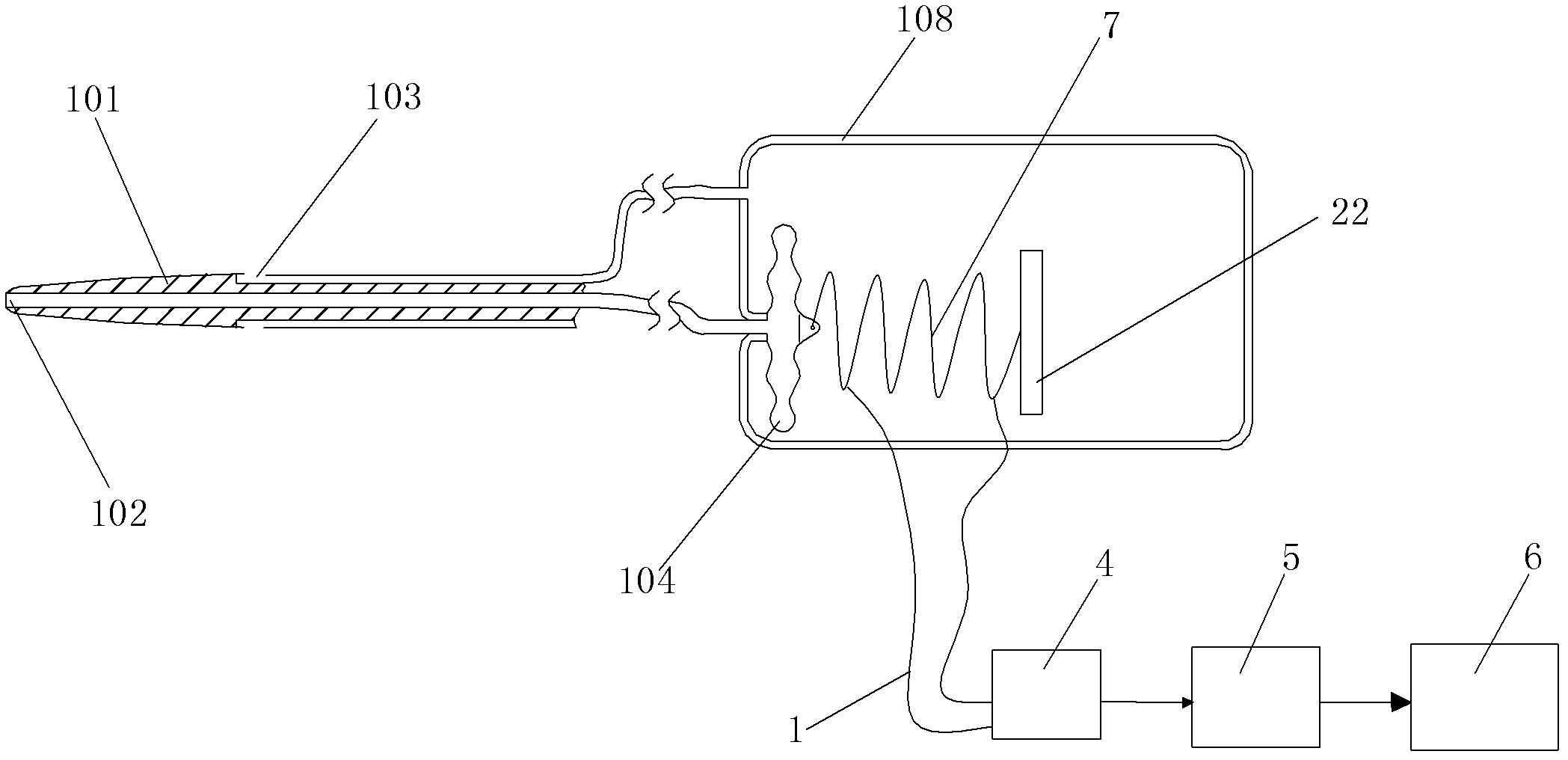
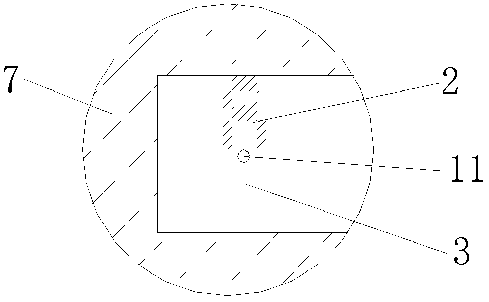
[0037] like figure 2 , image 3 A high-sensitivity fiber-optic airspeed measuring device shown includes a pitot tube 101, an open bellows 104, and a casing 108 containing the open bellows 104, in particular: the casing 108 contains an optical fiber bending sensing unit , the optical fiber bending sensing unit includes a curved test channel for the signal optical fiber 11 to pass through and a test unit 4 connected to the signal optical fiber 11 and synchronously testing the optical signal power variation in the signal optical fiber 11, the test The unit 4 is connected to the processing unit 5, and the processing unit 5 is connected to the display unit 6. The curved test channel includes a curved bracket and a plurality of A-side deformation teeth 2 continuously arranged on the upper and lower opposite sides of the curved bracket. and a plurality of B-side deformation teeth 3, a plurality of A-side deformation teeth 2 and a plurality of B-side deformation teeth 3 are arranged...

Embodiment 2

[0041] like Figure 4As shown, the difference between this embodiment and Embodiment 1 is that: one end of the signal optical fiber 11 contained in the curved housing 7 is provided with a light reflection device 16, and the light reflection device 16 is fixed on the inner wall of the housing 108, and the signal The other end of the optical fiber 11 is connected to the 1 port of the 1 × 2 optical splitter 15 through the optical cable 1, and the 2 ports of the 1 × 2 optical splitter 15 are connected to the test unit 4, so that the signal The optical signal transmitted in the optical fiber 11 passes twice through the curved housing 7 that bends the optical fiber, thereby further improving the sensing accuracy, and an auxiliary spring 8 is installed between the curved housing 7 and the base plate 9 . In this embodiment, the structures, connections and working principles of other parts are the same as those in Embodiment 1.

Embodiment 3

[0043] like Figure 5 , Image 6 As shown, in this embodiment, the difference from Embodiment 1 is that the curved support is a spring 12, and the deformation teeth 2 on the A side and the deformation teeth 3 on the B side are correspondingly arranged in the spring 12 with two adjacent coils of spring wire In between, and the A-side deformed teeth 2 and the B-side deformed teeth 3 are alternately arranged. In this embodiment, the structures, connections and working principles of other parts are the same as those in Embodiment 1.


PUM


Abstract

The invention discloses a high-sensitivity optical-type airspeed measuring device which comprises an airspeed pipe, a shell body and an opening sylphon. An optical curve sensing unit is contained inside the shell body, wherein the optical curve sensing unit comprises a curve-type test channel and a measuring unit, the measuring unit is connected with a disposing unit, and the disposing unit is connected with a display unit. The curve-type test channel comprises a curve-type support, multiple side A transformation teeth and multiple side B transformation teeth. The multiple side A transformation teeth and the multiple side B transformation teeth are arranged in a crossing mode, and the curve-type test channel which is provided for one or more signal optical fibers passing is formed among heads of the multiple side A transformation teeth and the multiple side B transformation teeth. The multiple side A transformation teeth and the multiple side B transformation teeth are arranged on two sides of the signal optical fibers correspondingly. A movable point of the opening sylphon is fixedly connected with one end of the curve-type support, and the other end of the curve-type support is fixed on the inner wall of the shell body. The high-sensitivity optical-type airspeed measuring device is simple in structure, reasonable in design, convenient to process and manufacture, low in cost and flexible in using manner, high in sensitivity and good in using effect.

Description

technical field [0001] The invention relates to an airspeed measuring device, in particular to a high-sensitivity optical fiber type airspeed measuring device. Background technique [0002] The measurement of airspeed plays a very important role in the safe flight and automatic driving of the aircraft. The traditional airspeed meter mainly has various methods such as differential pressure type, acceleration integral accumulation type and radar detection type. The acceleration integral accumulative method is to calculate the speed by measuring the acceleration first, and this method has accumulated errors; the radar detection method has high precision and is not affected by the climate. It is a relatively advanced measurement method, but it cannot use. Although the differential pressure type has relatively low accuracy, its structure is simple, and it is an effective method for measuring airspeed. [0003] The schematic diagram of the differential pressure airspeed gauge i...

Claims


Application Information

Patent Timeline
IPC IPC(8): G01P5/14
Inventor 杜兵
Owner XIAN JINHE OPTICAL TECH
Why Eureka
Try Eureka