Transformer electric conduction structure and transformer

A conductive structure and transformer technology, applied in the direction of transformer/inductor coil/winding/connection, transformer/inductor parts, circuits, etc., can solve the problem of not effectively reducing the output path of the transformer, reducing the volume of the loss transformer device, Affect circuit reliability and efficiency and other issues, to achieve the effect of improving space utilization, improving power density and efficiency, and reducing volume

Active Publication Date: 2013-06-05
DELTA ELECTRONICS (SHANGHAI) CO LTD
View PDF5 Cites 15 Cited by
  • Summary
  • Abstract
  • Description
  • Claims
  • Application Information

AI Technical Summary

Problems solved by technology

However, the high frequency has brought many problems to the winding design of the transformer: the skin effect and proximity effect of the wire under high frequency operation will cause additional losses between the transformer winding itself and the windings, and the high current output especially in the case of
[0004] The prior art also provides a transformer input and output side structure, such as figure 2 As shown, the primary side of the transformer is connected to the primary winding (201) and the switching element (202), and the left side of the switching element (202) is used as the input terminal; the secondary side of the transformer is connected to the secondary winding (203), and the output rectifier and the filter element (204), the right side of the rectification and filter element (204) is connected to the load; wherein, generally, the rectification and filter element (204) includes a rectifier and a filter, and the rectification and filter element (204) is installed on the PCB (Printed Circuit Board, printed circuit board, also known as printed circuit board), so that the distance between the lead wire of the secondary side winding (203) of the transformer and the rectifier is relatively large and the AC path is long, and the lead wire of the secondary side The upper impedance (ZP) (in a circuit with resistance, inductance and capacitance, the hindrance to alternating current is called impedance; both parasitic inductance and resistance) will have a large loss in high-frequency and high-current occasions, affecting the circuit reliability and efficiency; similarly, the path from the lead wire of the secondary winding (203) to the filter is relatively long, the DC loss on it is very large, and it takes up a lot of space on the PCB, which cannot be effectively reduced The output path of the transformer, reducing the loss and the volume of the transformer device

Method used


Image

  • Transformer electric conduction structure and transformer
  • Transformer electric conduction structure and transformer
  • Transformer electric conduction structure and transformer

Examples


Embodiment 2

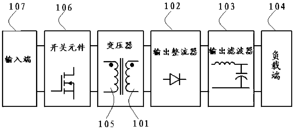
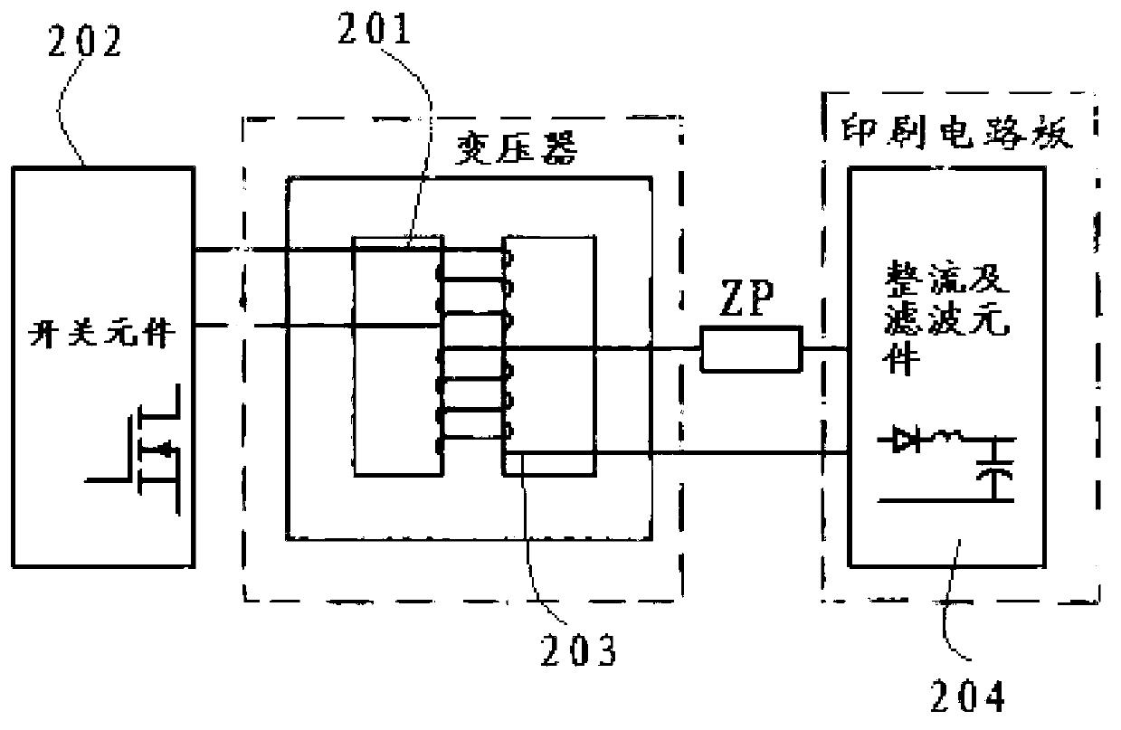
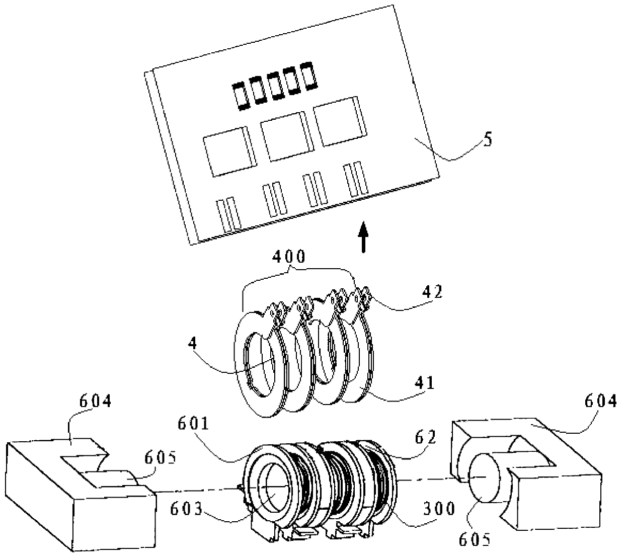
[0135] Such as Figure 7 As shown, the transformer of this embodiment is used to connect with the printed circuit board 5; it includes a primary winding 300, a plurality of conductive sheets 4 and a pair of magnetic core groups 604;

[0136] As an embodiment, the transformer of the present invention also includes a plurality of winding racks 6; the winding racks 6 are ring-shaped;

[0137] The magnetic core group 604 is provided with a protruding end 605. It should be noted that in this embodiment, the magnetic core group 604 is selected as a PQ type, but as an alternative to other embodiments of the present invention, the transformer adopts The magnetic core group can also choose other types;

[0138] The reel frame 6 is sleeved on the protruding end 605 of the magnetic core set 604;

[0139] The winding frame 6 is provided with a winding groove 62; the primary winding 300 is wound in the winding groove 62; the winding frame 6 wound with the primary winding 300 is set in th...


PUM


Abstract

The invention discloses a transformer electric conduction structure which comprises a main level winding unit (300), a printed circuit board (5) and a secondary winding unit (400) which is composed of a plurality of conducting chips (4). Each conducting chip (4) comprises an annular main body (41) and an output end (42) which is arranged on the outer edge of the annular main body (41) and protrudes towards outside. The annular main body (41) of each conducting chip (4) and the main level winding unit (300) are arranged in a stagger mode. The output end of each conducting chip (4) is directly connected with the printed circuit board (5) in a clamping mode. The invention further discloses a transformer, an output path of the transformer is effectively reduced, alternating current loss and direct current loss are reduced, the size of transformer components is reduced, and power density and efficiency of a power source are improved.

Description

technical field [0001] The invention relates to a conductive structure of a transformer and a transformer, in particular to a conductive structure of a transformer and a transformer which can effectively reduce the output path from the transformer to a circuit board and reduce AC loss and DC loss. Background technique [0002] Today, as power supplies are developing towards high power density, high efficiency, and low cost, the design of magnetic devices is becoming more and more important, and the design of power transformers is often the key. [0003] For example, figure 1 In the overall structure of the traditional DC / DC (direct current / direct current) converter shown, the secondary side of the transformer includes the transformer secondary winding (101), the output rectifier (102), the output filter (103) and the load terminal (104); the primary side of the transformer includes the primary winding (105), the switch element (106) and the input terminal (107); in the tran...

Claims


Application Information

Patent Timeline
Patent Type & Authority Applications(China)
IPC IPC(8): H01F27/29H01F27/30
CPCH01F2027/065H05K1/0263H05K2201/086H01F27/2866H05K1/165H05K2201/1034H05K1/18H05K3/328H01F27/2852H05K2201/10166
Inventor 吴洪洋王彬孙丽萍应建平
Owner DELTA ELECTRONICS (SHANGHAI) CO LTD
Why Eureka
Try Eureka