High speed D trigger based on transistor

A technology of transistors and flip-flops, applied in electric pulse generator circuits, pulse generation, electrical components, etc., can solve problems such as unsuitable for high-speed program frequency dividers, unsuitable for program frequency dividers, and high phase noise of frequency dividers. Achieve the effect of excellent phase noise characteristics, avoid mutual interference, and low phase noise

Inactive Publication Date: 2013-06-05
XIDIAN UNIV
View PDF4 Cites 2 Cited by
  • Summary
  • Abstract
  • Description
  • Claims
  • Application Information

AI Technical Summary

Problems solved by technology

[0006] 1) Slow working speed, not suitable for high-speed program frequency divider;
[0007] 2) The phase noise is high, which makes the phase noise of the whole program frequency divider high;
[0008] 3) Low operating frequency, not suitable for high-frequency program frequency divider

Method used


Image

  • High speed D trigger based on transistor
  • High speed D trigger based on transistor
  • High speed D trigger based on transistor

Examples


Embodiment Construction

[0028] In order to make the technical solution of the present invention clearer, the present invention will be further described in detail below in conjunction with specific embodiments and with reference to the accompanying drawings.

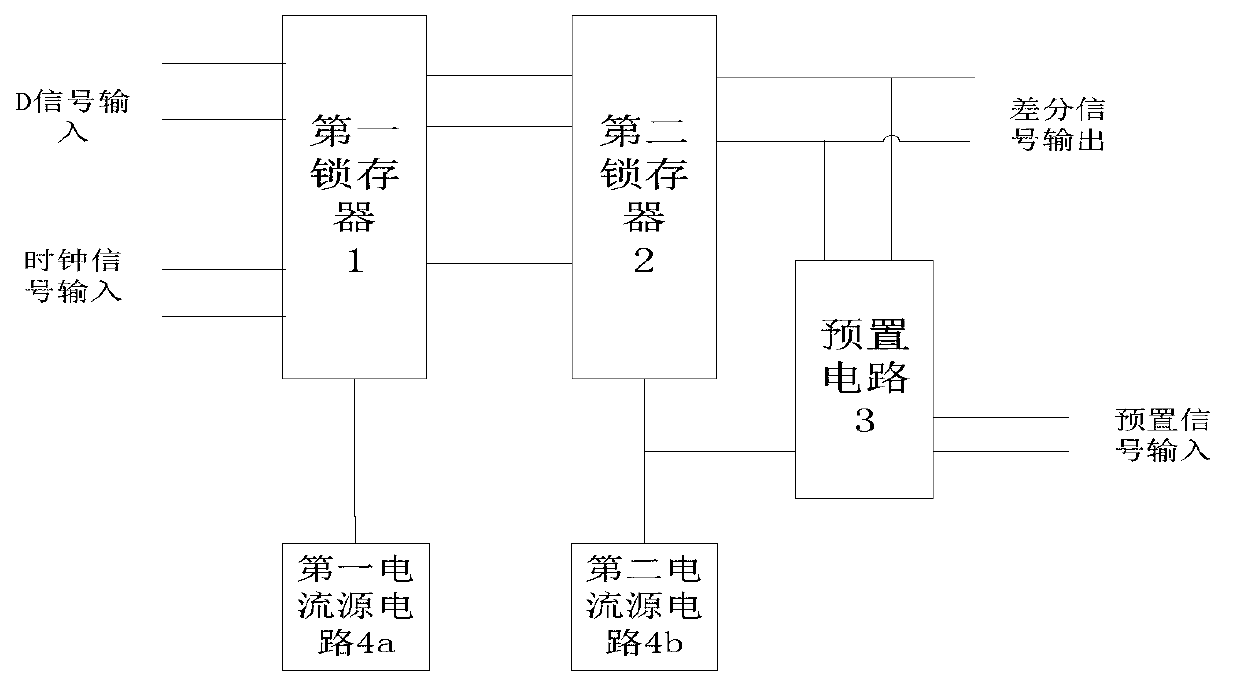
[0029] refer to image 3 , The high-speed D flip-flop provided by the present invention includes a first latch 1, a second latch 2, a preset circuit 3, a first current source circuit 4a and a second current source circuit 4b. Wherein, the input terminal of the second latch 2 is connected with the output terminal of the first latch 1; the output terminal of the second latch 2 is connected with the preset circuit 3, and the preset circuit 3 adopts a differential structure, and its pair The preset signal input by the external circuit is sampled and output; the first current source circuit 4a and the second current source circuit 4b are respectively connected to the first latch and the second latch and provide stable current for them; the external ...


PUM


Abstract

The invention discloses a high speed D trigger based on a transistor, and mainly solves the problems that an existing D trigger is high in phase noise and low in working frequency. The high speed D trigger based on the transistor mainly comprises a first latch (1), a second latch (2), a preset circuit (3), a first current source circuit (4a) and a second current source circuit (4b). The preset circuit (3) composed of a difference channel is connected with an output end of the second latch (2) and a current input end of the second latch (2). The preset circuit (3) is controlled by external signals to achieve a preset function. The first current source circuit (4a) is connected with a current input end of the first latch (1), and provides stable current for the first latch (1). The second current source circuit (4b) is connected with the current input end of the second latch (2), and provides stable current for the second latch (2). The high speed D trigger based on the transistor has the advantages of being simple in circuit, low in phase noise, high in working frequency, and the like. Accordingly, the high speed D trigger based on the transistor can be applied to a high speed program divider.

Description

technical field [0001] The invention belongs to the technical field of integrated circuit design and relates to a flip-flop, in particular to a high-speed D flip-flop based on a transistor HBT device, which can be used in a program frequency divider. technical background [0002] The program frequency divider is an important part of the phase-locked frequency synthesizer. Many important characteristics of the frequency synthesizer are related to the performance of the program frequency divider. For example, the working speed of the program frequency divider limits the output signal of the frequency synthesizer. the highest frequency, its phase noise affects the in-band phase noise of the frequency synthesizer. Therefore, it is extremely important for a high-performance frequency synthesizer to increase the speed of the program frequency divider and reduce the phase noise of the program frequency divider. [0003] The fundamental difference between the program frequency divi...

Claims


Application Information

Patent Timeline
Patent Type & Authority Applications(China)
IPC IPC(8): H03K3/012H03K3/02
Inventor 吕红亮刘一峰张金灿张义门张玉明周威
Owner XIDIAN UNIV
Why Eureka
Try Eureka