Laser tracker-based machine tool error dynamic compensation method

A technology of laser tracker and error dynamics, which is applied in the direction of automatic control devices, metal processing machinery parts, manufacturing tools, etc., can solve the problem of detection efficiency, detection accuracy and lack of versatility, and cannot meet the requirements of high-precision and fast detection. Interferometry has a long detection period and other problems, and achieves the effects of real-time tracking measurement, fast installation and fast response

Inactive Publication Date: 2013-06-12
CHONGQING UNIV
View PDF8 Cites 33 Cited by
  • Summary
  • Abstract
  • Description
  • Claims
  • Application Information

AI Technical Summary

Problems solved by technology

[0003] In the prior art, the error compensation methods of CNC machine tools are more common: physical reference measurement method, laser interferometry method, orthogonal grating measurement method, ballbar instrument, etc., due to the high precision of laser interferometer, laser interferometry The measurement method is more common in machine tool error compensation, but the detection cycle of the laser interferometry method is longer; and the above-mentioned other methods also have shortcomings in detection efficiency, detection accuracy and versatility, and cannot meet the high-precision and fast detection requirements; especially It is the compensation for the dynamic error of CNC machine tools, and there are obvious deficiencies

Method used


Image

  • Laser tracker-based machine tool error dynamic compensation method
  • Laser tracker-based machine tool error dynamic compensation method

Examples


Embodiment Construction

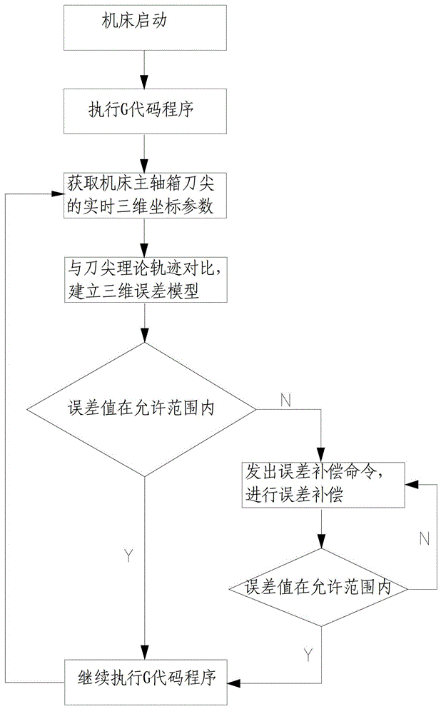
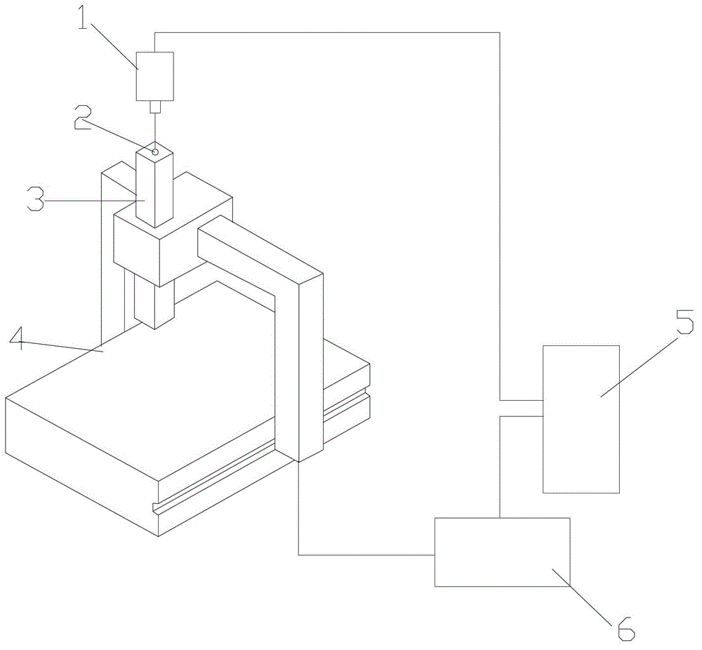
[0017] figure 1 It is a structural schematic diagram of the compensation system of the present invention, figure 2 It is a block diagram of the principle of the present invention, as shown in the figure: the method for dynamic compensation of machine tool errors based on laser trackers in this embodiment includes the following steps;

[0018] a. The machine tool 4 starts and executes the numerical control program (G code program), obtains the real-time three-dimensional coordinate parameters of the tool tip on the machine tool spindle box 3 through the laser tracker 1, and sends it to the computer 5;

[0019] b. Comparing the real-time three-dimensional coordinate parameters obtained in step a with the theoretical running trajectory of the tool tip on the machine tool spindle box 3 stored in the computer 5, establishing a three-dimensional space error model, and decomposing the tool tip on the machine tool spindle box 3 from the three-dimensional space error model The error...


PUM


Abstract

The invention discloses a laser tracker-based machine tool error dynamic compensation method. A laser tracker is adopted to perform dynamic tracking detection; and the method is suitable for being used in laboratory environments with strictly controlled temperature and humidity and can also be used in workshop site environments with severer conditions. Laser interference ranging, photoelectric detection, precision machinery, a computer and a control and modern numerical value calculation theory are integrated by the laser tracker; a space moving object is tracked and spatial three-dimensional coordinates of an object are measured in real time; and the method has the characteristics of high precision, high efficiency, real-time tracking measurement, quickness and convenience in mounting, easiness in operation and the like. A machine tool is dynamically monitored and compensated in real time based on a laser tracker measurement result; error measured by using the scheme is total error obtained after all system errors and random error are superposed; and thus, all error values can be dynamically compensated in real time by the scheme, the system precision of the machine tool is greatly improved, and a detection device of the machine tool is simplified.

Description

technical field [0001] The invention relates to a machine tool error processing method, in particular to a laser tracker-based dynamic compensation method for machine tool errors. Background technique [0002] The accuracy and precision stability of machine tools are important technical indicators of machine tools. According to the characteristics of mechanical movement, the error of the machine tool is difficult to achieve by simply improving the design, manufacture and assembly of parts to improve the accuracy of the machine tool and achieve high precision. Therefore, error compensation is one of the main ways for CNC machine tools to improve accuracy. [0003] In the prior art, the error compensation methods of CNC machine tools are more common: physical reference measurement method, laser interferometry method, orthogonal grating measurement method, ballbar instrument, etc., due to the high precision of laser interferometer, laser interferometry The measurement method ...

Claims


Application Information

Patent Timeline
Patent Type & Authority Applications(China)
IPC IPC(8): B23Q15/14B23Q17/24
Inventor 陶桂宝留成源谷立恒邵璟陈敏超樊星光王世桥
Owner CHONGQING UNIV
Why Eureka
Try Eureka