Automatic printer for vamp

A printing machine, automatic technology, applied in the direction of printing machine, rotary printing machine, printing, etc., can solve the problems that the printing quality is greatly affected, the position is easy to shift, and there cannot be too many through holes, so as to improve the printing effect and be practical Good performance, realize the effect of equipment integration and fully automatic operation

Inactive Publication Date: 2013-06-12
BLACK GOLD STEEL AUTOMATION TECH FUJIAN
View PDF8 Cites 24 Cited by
  • Summary
  • Abstract
  • Description
  • Claims
  • Application Information

AI Technical Summary

Problems solved by technology

[0002] At present, in the shoe industry, clothing and luggage industry, there are many flat materials that need to be printed, such as shoe upper printing or printing on luggage. Before printing, all substrate materials have been cut. In the feeding process, the general industry uses manipulator or vacuum adsorption to lay the material. The manipulator is to use the manipulator to lay the stacked substrates that need to be printed on the printing table, and then print; vacuum adsorption Spreading is to use vacuum adsorption to absorb the substrate, then transfer it to the printing table, and then print; although these methods can realize automatic spreading, there are some shortcomings and shortcomings: 1. When the manipulator is laying the material, The position where the substrate is laid is easy to shift. In the actual production process, the material spreading effect is not good. When processing the substrate with high printing accuracy requirements, it has a considerable impact on the printing quality; 2. Use vacuum adsorption When laying the material, it has certain requirements for the substrate. The substrate must have a certain adsorption area, and the surface should not have too many through holes. If the substrate is too heavy or too thick, it cannot be adsorbed; 3. Vacuum adsorption consumption can

Method used


Image

  • Automatic printer for vamp
  • Automatic printer for vamp
  • Automatic printer for vamp

Examples


Embodiment Construction

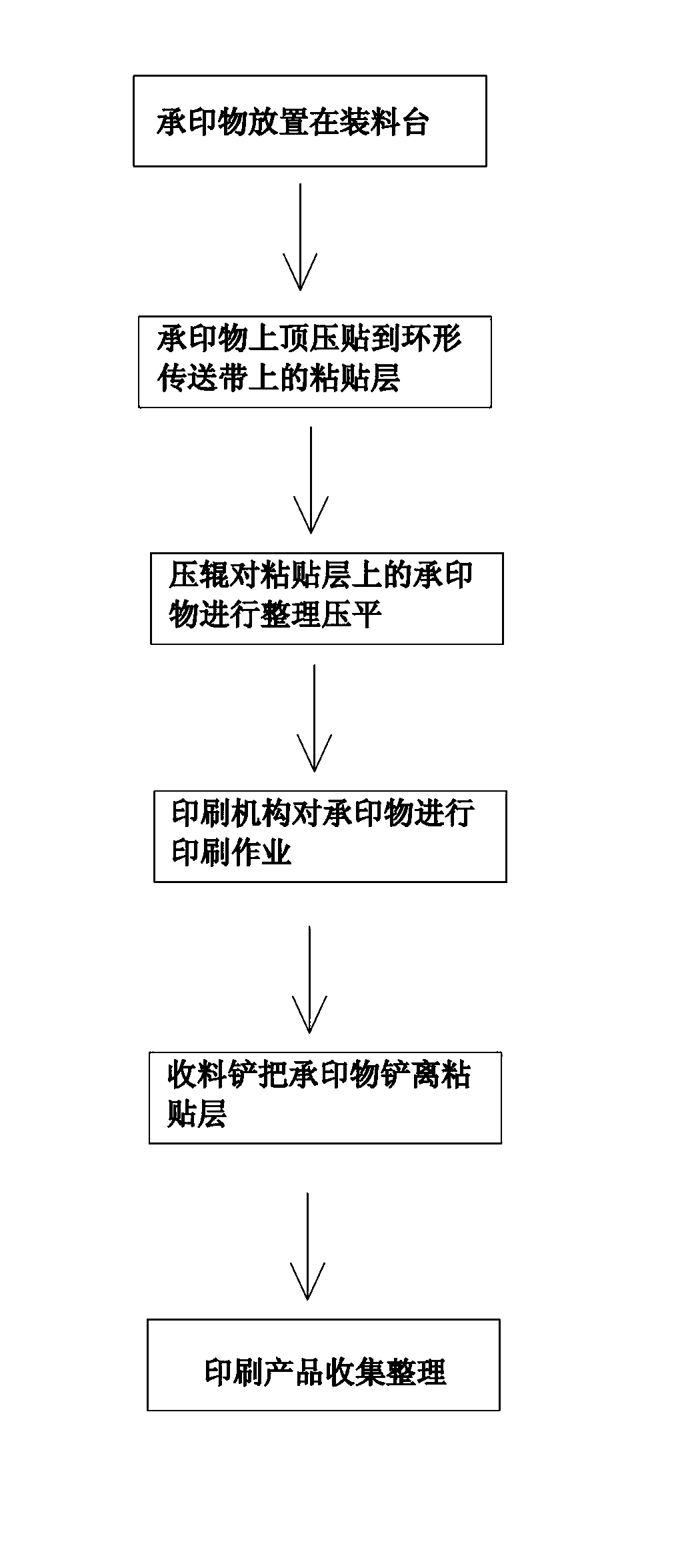
[0019] The specific implementation manner of the present invention will be further described below with reference to the accompanying drawings.

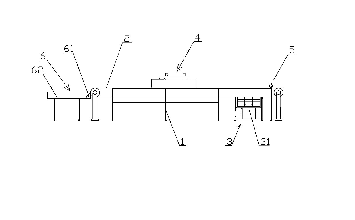
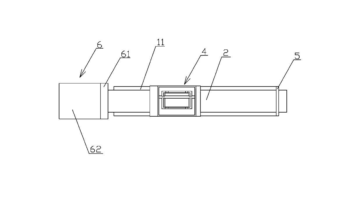
[0020] Such as figure 1 , figure 2 As shown, an automatic printing machine for shoe uppers includes a combined frame body 1 provided with a working platform 11 on which an endless conveyor belt 2 and a servo motor (figure 1) for driving are provided on the combined frame body 1 not shown in), the surface of the endless conveyor belt 2 is coated with a layer of adhesive layer that can change the adhesive strength according to the specific substrate (due to the viewing angle, it is not shown in the figure); the bottom of the combined frame body 1 is provided with a The feeding mechanism 3 for pressing the printed matter on the above-mentioned adhesive layer, the feeding mechanism 3 includes a lifting table 31 for neatly holding the printed matter and its associated lifting device (not shown in the figure) ).

[0021] Such as figur...


PUM


Abstract

The invention discloses an automatic printer for a vamp. The automatic printer comprises a combined rack body on which a working platform is arranged, wherein an annular conveyor belt and a driving device of the conveyor belt are arranged on the combined rack body, and an adhesion layer with changeable adhesion strength is coated on the surface of the annular conveyor belt; a material feeding mechanism is arranged below the combined rack body and is used for upwards propping against a printed object to press and adhere the printed object on the adhesion layer; and a printing mechanism is arranged above the combined rack body and is used for printing the printed object. According to the automatic printer for the vamp, which is disclosed by the invention, firstly the printed object is temporally adhered on the annular conveyor belt to be arranged and flattened and then is printed, secondly the printed object is automatically shoveled out of the annular conveyor belt by a material collection shovel, and finally product collection processing is carried out; and therefore, through the new conveying and printing operation manner, the printing precision and the printing quality of a printing mechanism are improved.

Description

technical field [0001] The invention relates to a printing machine, more specifically an automatic printing machine for shoe uppers. Background technique [0002] At present, in the shoe industry, clothing and luggage industry, there are many flat materials that need to be printed, such as shoe upper printing or printing on luggage. Before printing, all substrate materials have been cut. In the feeding process, the general industry uses manipulator or vacuum adsorption to lay the material. The manipulator is to use the manipulator to lay the stacked substrates that need to be printed on the printing table, and then print; vacuum adsorption Spreading is to use vacuum adsorption to absorb the substrate, then transfer it to the printing table, and then print; although these methods can realize automatic spreading, there are some shortcomings and shortcomings: 1. When the manipulator is laying the material, The position where the substrate is laid is easy to shift. In the actua...

Claims


Application Information

Patent Timeline
Patent Type & Authority Applications(China)
IPC IPC(8): B41F17/00
Inventor 阙小鸿
Owner BLACK GOLD STEEL AUTOMATION TECH FUJIAN
Why Eureka
Try Eureka