Lead wire rotary drying machine

A dryer and lead wire technology, which is applied in drying, drying solid materials, lighting and heating equipment, etc., can solve the problems of long drying time for lead wires, high labor intensity, large floor space, etc., and achieve the cost of lead wire drying Low cost, easy manufacturing and maintenance, and low heat consumption

Inactive Publication Date: 2013-06-12
JIANGXI JIALIAN TECH
View PDF0 Cites 2 Cited by
  • Summary
  • Abstract
  • Description
  • Claims
  • Application Information

AI Technical Summary

Problems solved by technology

Since the lead wire is inflammable, in order to prevent the lead wire from burning or even explode, and to ensure the safety of the lead wire production, the first method of drying the lead wire is to use the traditional method of drying the lead wire together with the frame under a sunny day. Here comes the following problems: the open-air drying of lead wires takes up a large area, and multiple people are required to manage them specially. The transfer work is labor-intensive and is greatly affected by the weather. The drying time of lead wires is long, and the drying efficiency of lead wires is low, which cannot meet the needs of lead wires. ; In addition to the traditional way of drying the lead wires, there are also tunnel hot gas furnaces and through-type hot gas drying furnaces for the lead wire drying. Although these two lead wire drying equipments have improved the efficiency of the lead wire drying, their common disadvantages are The structure of the equipment is complex and bulky, not only occupies a large area, but also consumes a lot of heat and energy, and the drying cost is high

Method used


Image

  • Lead wire rotary drying machine
  • Lead wire rotary drying machine
  • Lead wire rotary drying machine

Examples


Embodiment Construction

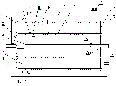
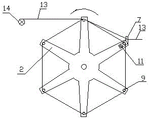
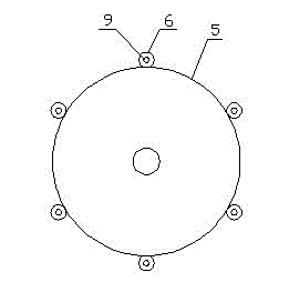
[0011] exist figure 1 , figure 2 and image 3 Among them, the lead wire rotary dryer includes a turret movably arranged on the box body, the box body is composed of an upper box body 15 and a lower box body 1, and the box body is provided with a hot air hole 12 and an air outlet hole 10 , the hot air hole is connected to the hot air source through the pipe, and the air outlet is connected to the exhaust device through the pipe. The temperature of the hot air can be controlled at 50--60°C. The turret includes a rotating shaft 4, a gear plate 5, a support plate 2, a nut sleeve 8, Guide rod 11 and screw mandrel 9, described turret is preferably positive hexagonal, and support plate is made up of six rib plates and central circular plate, and six screw mandrels are arranged on six corners of two support plates in the form of annular intervals. The turret can also be set as a regular square (four screw rods) or pentagon (five screw rods) or other regular polygons. The number of ...


PUM


Abstract

The invention discloses a lead wire rotary drying machine which comprises a rotating frame movably arranged on a box body; the rotating frame comprises a rotating shaft (4), a gear wheel (5), support plates (2), a nut sleeve (8), a guide rod (11) and screw rods (9); the screw rods are movably arranged between the two support plates at intervals in an annular manner; the support plates are arranged at the two ends of the rotating shaft; the gear wheel located on the left sides of the support plates are arranged at the left end of the rotating shaft; one end of each screw rod extends out of the supporting plate and is connected with a pinion wheel (6); the pinion wheel is meshed with the gear wheel; the nut sleeve is sleeved at one end of one of the screw rods; the lower end of the nut sleeve is supported on the guide rod; the two ends of the guide rod are arranged on the support plates; a magnetic clip capable of being penetrated by lead wires is fixedly arranged on the nut sleeve; and the screw rods can rotate with the gear wheel and can rotate simultaneously on themselves. The lead wire rotary drying machine provided by the invention has the advantages of simple and compact structure, small occupied area, convenience in manufacture and maintenance, high lead wire drying efficiency, low heat consumption, and low lead wire drying cost.

Description

technical field [0001] The invention relates to a drying machine, in particular to an efficient and safe automatic wire drying machine for drying wires. Background technique [0002] Firecrackers and fireworks are people's favorite festive consumer products, which can bring joy to people and add color to holidays. With the continuous improvement of people's living standards, the output of firecrackers and fireworks has also increased rapidly. As we all know, the lead wire is an important part in the manufacture of firecrackers and fireworks. It not only requires good quality, but also consumes a lot. At present, most of the lead wires are made of paper wrapped with nitrate, and the paper is wound in a spiral shape by a rotating mechanism, then dipped in glue, and then wound on the frame for drying and forming. Since the lead wire is flammable, in order to prevent the lead wire from burning or even explode, and ensure the safety of the lead wire production, the first meth...

Claims


Application Information

Patent Timeline
Patent Type & Authority Applications(China)
IPC IPC(8): F26B25/00
Inventor 章明琦甘增兵
Owner JIANGXI JIALIAN TECH
Why Eureka
Try Eureka