

Brillouin optical time domain reflectormeter method and device based on parallel data processing technique
An optical time domain reflectometer and data processing technology, applied in the field of sensing, can solve problems such as inability to realize dynamic measurement of temperature and stress
- Summary
- Abstract
- Description
- Claims
- Application Information
AI Technical Summary
Problems solved by technology
Method used
Image

Examples
Embodiment 1
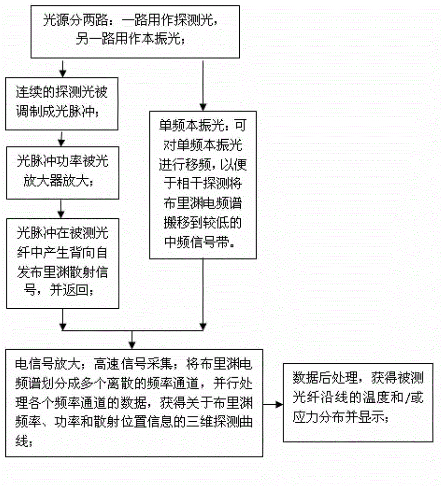
[0034] See figure 1 , a method of Brillouin optical time domain reflectometer based on parallel data processing technology provided by the embodiment of the present invention, the detailed content of the method is as follows:
[0035] The laser light emitted by the single-frequency laser source is divided into two paths by the coupler, one path is modulated into optical pulses by the optical pulse modulator, and the other path is used as single-frequency local oscillator light;
[0036] The optical pulse is first injected into the optical fiber under test after the peak power is increased by the optical amplifier, and the local oscillator light is shifted by a frequency shifter to make the difference frequency of the self-published Brillouin scattering signal generated by the optical pulse in the optical fiber under test falls within the bandwidth of the detector;
[0037] The spontaneous Brillouin scattering signal generated by the optical pulse in the optical fiber under te...
Embodiment 2
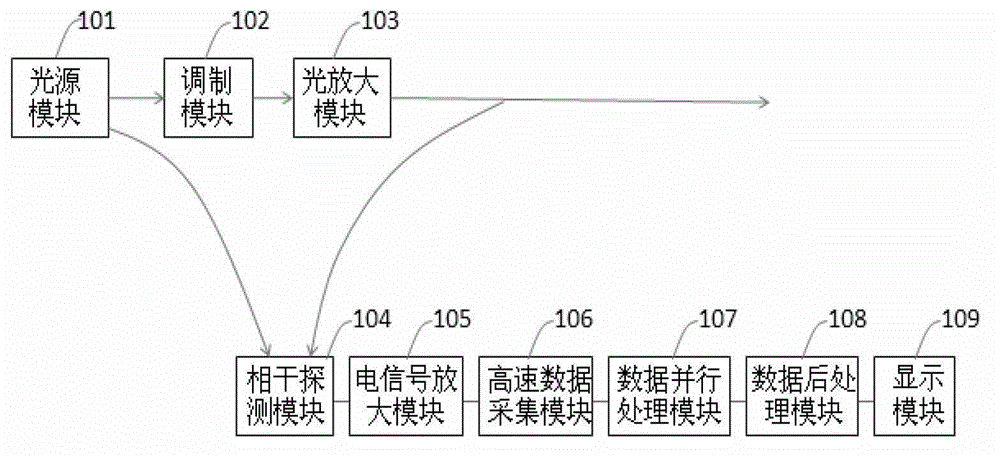
[0041] See figure 2 , the embodiment of the present invention provides a Brillouin optical time domain reflectometer method and device based on parallel data processing technology, the method and device details are as follows:
[0042] The light source module 101 is composed of a single-frequency laser and a 90:10 Y-type coupler. The single-frequency laser is divided into two beams by the coupler. One beam with high power is used as the probe light, while the other beam is used as the local oscillator light and Direct access to the coherent detection module 104;
[0043]The continuous detection light enters the modulation module 102, the modulation module 102 is composed of an electro-optic modulator and its drive, the continuous detection light is modulated into a detection light pulse and its frequency is shifted up by about 10.8 GHz, so that the pulse generated in the optical fiber under test The anti-Stokes spectrum in the spontaneous Brillouin scattered light is close t...
Embodiment 3
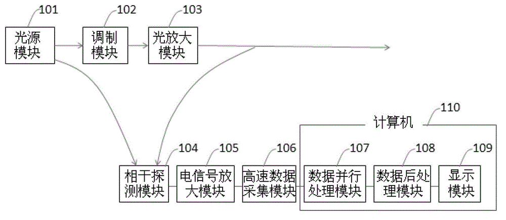
[0053] See image 3 , the embodiment of the present invention provides a Brillouin optical time domain reflectometer method and device based on parallel data processing technology, the method and device details are as follows:
[0054] The light source module 101 is composed of a single-frequency laser and a 90:10 Y-type coupler. The single-frequency laser is divided into two beams by the coupler. One beam with high power is used as the probe light, while the other beam is used as the local oscillator light and Direct access to the coherent detection module 104;
[0055] The continuous detection light enters the modulation module 102, the modulation module 102 is composed of an electro-optic modulator and its drive, the continuous detection light is modulated into a detection light pulse and its frequency is shifted up by about 10.8 GHz, so that the pulse generated in the optical fiber under test The anti-Stokes spectrum in the spontaneous Brillouin scattered light is close t...
PUM
 Abstract
Description
Claims
Application Information