Calibrating method for CCD (Charge Coupled Device) imaging lateral laser radar

A technology of lateral laser radar and calibration method, which is applied in the field of calibration of CCD imaging lateral laser radar, can solve problems such as errors and inability to measure the atmospheric extinction coefficient, and achieve the goals of improving measurement accuracy, increasing the scope of application, and ensuring accuracy Effect

Inactive Publication Date: 2013-06-12
中国人民解放军陆军军官学院
View PDF4 Cites 19 Cited by
  • Summary
  • Abstract
  • Description
  • Claims
  • Application Information

AI Technical Summary

Problems solved by technology

However, there are deficiencies in this measurement method. First of all, the CCD camera is required to be at a small angle with the laser, and what the CCD receives is only the backscattered light of the laser in the atmosphere, making it only suitable for laser scattering angles of approximately 180 degrees. Measurement; secondly, although the distribution of the laser echo signal with different distances is obtained through distance geometric correction, it is not considered that the CCD camera is composed of multiple pixels, and the incident angles of the beams of scattered light irradiating different pixels are not the same The characteristics of different pixels are used to calibrate the corresponding opening angle, which makes the measurement results have certain errors; finally, only the atmospheric extinction coefficient in the horizontal direction of the surface can be measured, and the atmospheric extinction coefficient at different heights cannot be measured.

Method used


Image

  • Calibrating method for CCD (Charge Coupled Device) imaging lateral laser radar
  • Calibrating method for CCD (Charge Coupled Device) imaging lateral laser radar
  • Calibrating method for CCD (Charge Coupled Device) imaging lateral laser radar

Examples


Embodiment Construction

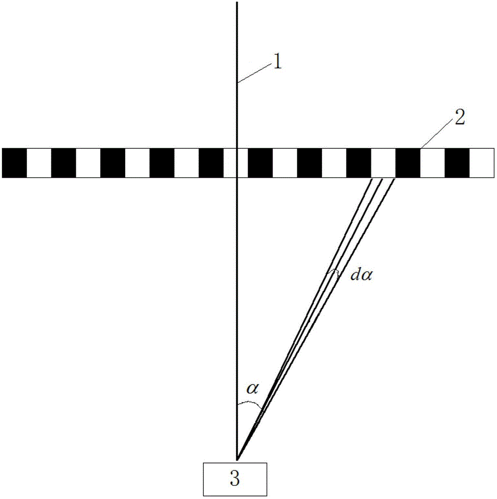
[0014] see figure 1 , figure 2 with image 3 , the calibration method of CCD imaging lateral lidar is as follows:

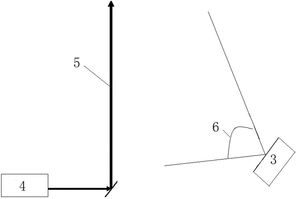
[0015] Step 1, after the optical axis 1 of the CCD camera is perpendicular to the plane of the calibration table 2, first use the CCD camera 3 to obtain the CCD image of the calibration table 2; wherein, the opening angle 6 of the CCD camera 3 is 9° (it can be 60-120° ) degrees, the vertical distance between the CCD camera 3 and the calibration table 2 is 5 (can be 5-10) m, and the calibration table 2 is a single-line table, and the table is a black and white square table with a side length of 1 cm. Then calculate the deflection angle α and angular width dα of each pixel from the number of the table in the CCD image of the calibration table 2 and the number of the pixel in the same dimension as the increment of the table number in the table.

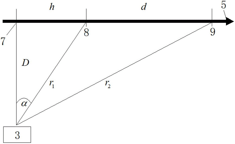
[0016] Step 2, after placing the CCD camera 3 near the side of the laser radar emission beam 5, first use the three-p...


PUM

PropertyMeasurementUnit
Zhang jiaoaaaaaaaaaa

Abstract

The invention discloses a calibrating method for a CCD (Charge Coupled Device) imaging lateral laser radar. The method comprises the following steps of: enabling an optical axis (1) of a CCD camera to be vertical to the plane of a calibration table (2), firstly acquiring a CCD image of the calibration table (2) by use of the CCD camera (3), and then calculating the offset angle (alpha) and angle width (d alpha) of each pixel according to a table number in the CCD image of the calibration table (2) and a pixel number with a same dimension as the table number increment in the table; and after placing the CCD camera (3) at the lateral adjacent part of an emitted light beam (5) of the laser radar, firstly determining the vertical distance(D) between the CCD camera (3) and the emitted light beam (5) of the laser radar by adopting a three-point positioning method, then substituting the offset angle (alpha) and angle width (d alpha) of each pixel as well as the vertical distance (D) between the CCD camera (3) and the emitted light beam (5) of the laser radar into a lateral laser radar equation P(alpha)=P0KA / D *TtTrbeta(alpha)dalpha, and performing inversion calculation by use of the offset angles (alpha), the angle widths (d alpha) and the vertical distance (D) so as to obtain atmospheric parameters. The calibrating method disclosed by the invention is high in measurement accuracy and wide in application range, and can be widely used for measuring the spatial distribution of atmospheric aerosol of a surface layer.

Description

technical field [0001] The invention relates to a laser radar calibration method, in particular to a CCD imaging lateral laser radar calibration method. Background technique [0002] At present, in order to realize the measurement of atmospheric visibility or extinction coefficient, lidar is often used. For example, the Chinese invention patent application CN 102621102 A published on August 1, 2012 a "Measurement method of horizontal visibility based on CCD lidar". The invention patent application document discloses a continuous laser as the emission light source, using the optical receiving component composed of a CCD camera and a filter in series to receive the laser echo signal from within several kilometers, and analyze the laser echo image through the computer After processing, the atmospheric extinction coefficient is obtained, so as to obtain the size of the atmospheric horizontal visibility. However, there are deficiencies in this measurement method. First of all, ...

Claims


Application Information

Patent Timeline
IPC IPC(8): G01S7/497
Inventor 陶宗明陈向春戴玮梅洛勤储德林陈宇张清泽
Owner 中国人民解放军陆军军官学院
Why Eureka
Try Eureka