Aligning method of unmarked deep-anaglyph micro lens array and detector

A technology of microlens array and deep relief, which is applied in the direction of lens, instrument, photoplate making process of pattern surface, etc. It can solve the problem that the deep relief microlens array cannot be aligned with high precision of visible light or infrared detector.

Active Publication Date: 2015-01-07
INST OF OPTICS & ELECTRONICS - CHINESE ACAD OF SCI
View PDF7 Cites 0 Cited by
  • Summary
  • Abstract
  • Description
  • Claims
  • Application Information

AI Technical Summary

Problems solved by technology

[0004] In order to solve the problem that the traditional mark alignment method of the microlens array cannot meet the high-precision alignment problem between the deep relief microlens array and the visible light or infrared detector, the purpose of the present invention is to provide a mark-free deep relief microlens array and detector. Alignment method

Method used


Image

  • Aligning method of unmarked deep-anaglyph micro lens array and detector
  • Aligning method of unmarked deep-anaglyph micro lens array and detector
  • Aligning method of unmarked deep-anaglyph micro lens array and detector

Examples


Embodiment 1

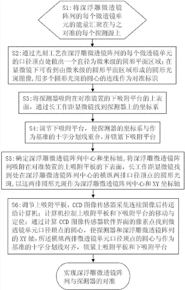
[0048] Embodiment 1: If the alignment accuracy of the deep-relief microlens array and the detector is required to be 0.001 mm, the specific alignment scheme is as follows:

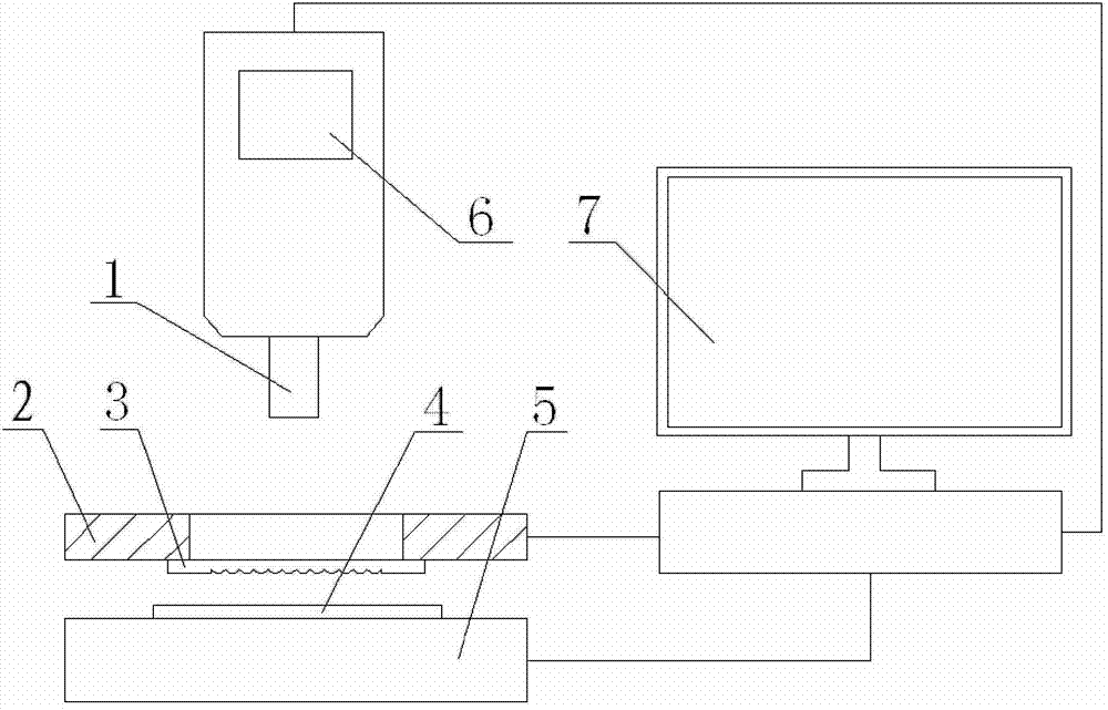
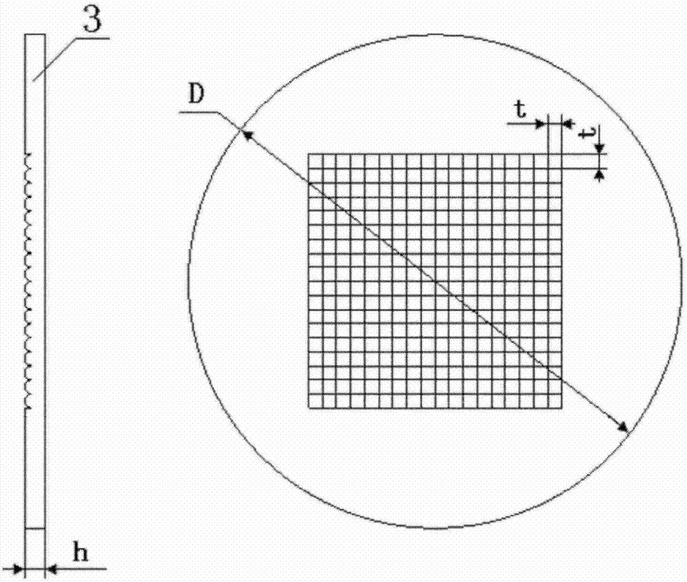
[0049] 1) if figure 2 The deep relief microlens array structure is shown, and the deep relief microlens array 3 is adopted. The deep relief microlens array 3 is composed of 18×18 microlens units 31, and each microlens unit 31 is a convex spherical surface, a square aperture, and a relief The depth is 20 μm, wherein the diameter side length of the microlens unit is t=0.3mm, the outer diameter of the deep-relief microlens array substrate is D=11mm, and the thickness of the deep-relief microlens array substrate is h=0.6mm; the deep-relief microlens array 3 can be with Figure 4 The square caliber used among the shown present invention is a * a=0.26mm * 0.26mm (wherein a is 41 caliber side lengths of detection source), the spacing b=0.08mm of each detection source 41, and detection source 41 quantity is 18 *...


PUM

PropertyMeasurementUnit
thicknessaaaaaaaaaa

Abstract

Disclosed is an aligning method of an unmarked deep-anaglyph micro lens array and a detector. The aligning method comprises that a circular plane area with diameter being microns is formed in the top point portion of aperture of each micro lens unit through photolithography technique. An X axis and a Y axis of the micro lens array can be confirmed according to lines of two rows of top point centers at the center of the array under the microscope, wherein the two rows of the top point centers are respectively in the horizontal direction and the vertical direction. A cross division line serves as a criterion of aligning so as to adjust and align a used self-control device, wherein the division line stays the same position on a software interface of a charge coupled device (CCD) image sensor, the detector and the X axis and the Y axis of the micro lens array are respectively aligned with the cross division line which serves as the criterion, and therefore alignment of the micro lens array and the detector is achieved. According to the method, unit aperture top points in the deep-anaglyph micro lens array serve as actual aligning marks, and the problem in a mark aligning method that aligning accuracy is low caused by bad etching edge steep degree, mark drifting and the like is solved.

Description

technical field [0001] The invention relates to an alignment method of a markless deep-relief microlens array and a detector, which belongs to the innovation of the alignment method of the microlens array. Background technique [0002] Visible light or infrared focal plane array detectors have a "dead zone" for signal line wiring due to structural layout and microfabrication limitations, so that the duty ratio of the photosensitive area in the entire detector area can only reach 30% to 90%. It is difficult to obtain a higher filling rate. Microlens array technology is a new technology that can enhance detector fill factor and sensitivity. Using the wavefront modulation and light wave convergence characteristics of the microlens array, the incident light is deflected and converged to the photosensitive area of ​​each detector element, and a 100% duty cycle can be obtained, which is expected to increase the duty cycle of the entire detector to more than 90%. , effectively im...

Claims


Application Information

Patent Timeline
Patent Type & Authority Patents(China)
IPC IPC(8): G02B3/02G03F9/00
Inventor 罗先刚王彦钦王长涛张鸶懿
Owner INST OF OPTICS & ELECTRONICS - CHINESE ACAD OF SCI
Why Eureka
Try Eureka