Signal conditioning circuit for detecting thickness of yarn

A signal conditioning circuit and thickness technology, applied in the field of electronic technology applications, can solve the problems of high cost of PGA circuit, multi-cut, signal zero drift, etc., to achieve intelligent zero adjustment and gain control, overcome environmental changes and solve zero. The effect of bit drift

Active Publication Date: 2013-06-12
ZHEJIANG KANGLI AUTOMATIC CONTROL TECH
View PDF5 Cites 13 Cited by
  • Summary
  • Abstract
  • Description
  • Claims
  • Application Information

AI Technical Summary

Problems solved by technology

In the traditional photoelectric electronic yarn clearer, the output signal of the infrared receiving tube is mainly adjusted by a fixed gain amplifier circuit, which limits the detection range of yarn thickness and affects the detection accuracy
On the one hand, changes in the illumination in the environment and flying flowers and dust during the working process of the textile machine will cause the zero position drift of the signal, resulting in frequent missed and multi-cut yarn defects after the electronic yarn clearer has been used for a period of time.
On the other hand, the electronic yarn clearer needs to adapt to the identification of yarn defects of yarns with different counts and twists, and the amplifier circuit with fixed gain cannot realize the self-adaptation of yarn counts.
Although the gain of the amplifier can also be adjusted with a dedicated programmable amplifier (PGA) circuit, the accuracy of the gain adjustment is low, and the cost of the PGA circuit is relatively high

Method used


Image

  • Signal conditioning circuit for detecting thickness of yarn
  • Signal conditioning circuit for detecting thickness of yarn
  • Signal conditioning circuit for detecting thickness of yarn

Examples


Embodiment Construction

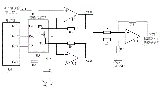
[0014] Such as figure 1 As shown, a signal conditioning circuit for yarn thickness detection includes a digital control potentiometer control circuit, a DC zero-adjustment signal generation circuit, and an instrumentation amplifier circuit.

[0015] The digital control potentiometer control circuit includes single-chip microcomputer STM8S105C6T6 chip U4 and numerical control potentiometer X9313WS chip U5; the I / O1 port of the single-chip microcomputer STM8S105C6T6 chip U4 is connected to the U / D pin of the numerical control potentiometer, and the I / O2 port of the single-chip microcomputer STM8S105C6T6 chip U4 is connected to the digital control potentiometer The INC pin of the potentiometer is connected, and the I / O3 port of the STM8S105C6T6 chip U4 is connected to the CS pin of the digital control potentiometer.

[0016] The DC zero-adjusting signal generating circuit includes a single-chip microcomputer STM8S105C6T6 chip U4, a second resistor R2 and a first capacitor C1; the...


PUM


Abstract

The invention discloses a signal conditioning circuit for detecting the thickness of a yarn. The signal conditioning circuit for detecting the thickness of the yarn is poor in self adaptation to different yarns at present. The signal conditioning circuit comprises a numerical control potentiometer control circuit, a direct current zero setting circuit and an instrument amplifier circuit. The numerical control potentiometer control circuit comprises a single chip microcomputer and a numerical control potentiometer, the direct current zero setting circuit comprises a single chip microcomputer, a resistor and a capacitor, and the instrument amplifier circuit comprises three operational amplifiers and seven resistors. The signal conditioning circuit conducts RC filtering on pulse-width modulation (PWM) signals output by the single chip microcomputers, then the PWM signals and signals output by an infrared receiving tube serve as a pair of difference signals to be input in the instrument amplifier circuit with controllable gain, and accordingly the signal conditioning circuit is guaranteed to have intelligent zero setting and an automatic gain adjusting function.

Description

technical field [0001] The invention belongs to the application field of electronic technology, specifically textile electronic technology, and specifically relates to a signal conditioning circuit for yarn thickness detection. Background technique [0002] Electronic yarn clearer is an electronic device used in the textile industry to remove harmful yarn defects and control yarn quality. The application of electronic yarn clearer can not only monitor the working status of the previous process, but also greatly improve the quality and work efficiency of the finished product in the subsequent process. According to different detection principles, electronic yarn clearers can be divided into two types: photoelectric and capacitive. Compared with the capacitive electronic yarn clearer, the photoelectric electronic yarn clearer has the advantage of having little influence on the ambient temperature and humidity. In the traditional photoelectric electronic yarn clearer, the outp...

Claims


Application Information

Patent Timeline
Patent Type & Authority Applications(China)
IPC IPC(8): G05B19/042
Inventor 高明煜徐英杰曾毓黄继业何志伟吴占雄马国进
Owner ZHEJIANG KANGLI AUTOMATIC CONTROL TECH
Why Eureka
Try Eureka