
Horn basin frame for improving voice coil concentricity and manufacture method for horn

A technology of a speaker cone frame and a manufacturing method, which is applied to the fixing/tightening of the diaphragm, sensors, electrical components, etc., can solve the problems of inability to guarantee the dimensional accuracy, increase the cost of drum paper, hinder the vibration of the voice coil, etc. The effect of stability, improved yield and improved reliability

Inactive Publication Date: 2013-06-12
东星电声科技(东莞)有限公司
View PDF4 Cites 10 Cited by
  • Summary
  • Abstract
  • Description
  • Claims
  • Application Information

AI Technical Summary

Problems solved by technology

Similar to this kind of products, the traditional positioning method is to use the outer diameter of the drum paper ring and the retaining wall on the bonding surface of the basin frame to locate. The biggest problem with this method is that the outer ring of the drum paper is usually a softer material, which If the tolerance is large, there will be the problem of inaccurate positioning, which will cause the voice coil to move or tilt, and even deviate to the side of the through hole to contact the magnetic circuit of the magnetic component. The dimensional accuracy cannot be guaranteed, thus hindering the vibration of the voice coil, resulting in The sound quality is poor and the product yield rate is low; and if the dimensional tolerance of the outer ring of the drum paper folding ring is to be small, it is necessary to use a harder material, but this obviously increases the cost of the drum paper

Method used


Image

  • Horn basin frame for improving voice coil concentricity and manufacture method for horn
  • Horn basin frame for improving voice coil concentricity and manufacture method for horn
  • Horn basin frame for improving voice coil concentricity and manufacture method for horn

Examples


Embodiment Construction

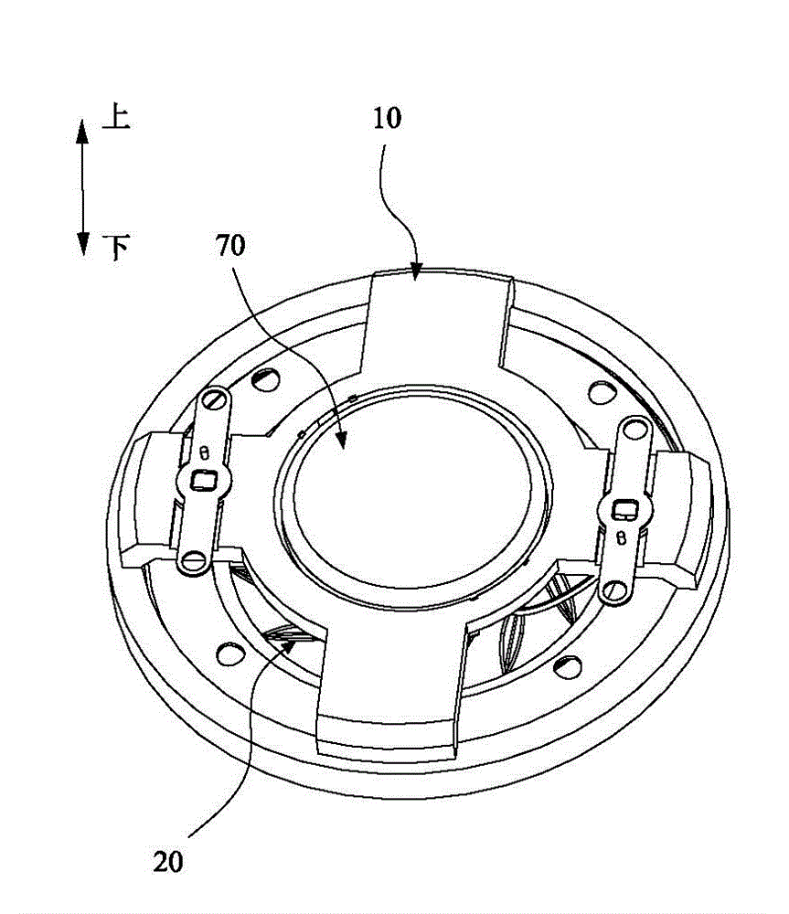
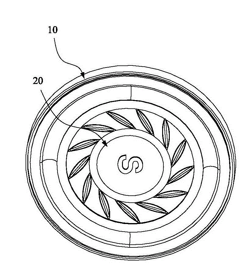
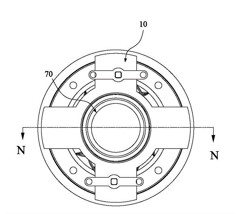
[0054] Please refer to Figure 1 to Figure 7 As shown, it shows the specific structure of the preferred embodiment of the present invention, including a circular basin frame 10, drum paper 20, double folding ring 30, voice coil 40 and a magnetic component, which in turn includes an outer cover 70 and a magnetic circuit arranged inside the outer cover 70. The magnetic circuit is composed of a magnet 60 and a washer 50 stacked up and down. The centers of the frame 10, the drum paper 20, the voice coil 40, the washer 50, the magnet 60 and the outer cover 70 are on the same straight line.

[0055] The up and down directions mentioned in the text of this embodiment are figure 1 The direction indicated shall prevail.

[0056] Wherein, the basin frame 10 includes an inner ring portion 11, an outer ring portion 12, and a plurality of frames 13 connected between the inner ring portion 11 and the outer ring portion 12. The inner ring portion 11 and the top of the frame 13 are flush with each...


PUM


Abstract

The invention discloses a horn basin frame for improving voice coil concentricity and a manufacture method for the horn. The horn basin frame comprises an inner ring, an outer ring and a skeleton which is connected between the inner ring and the outer ring in an overlapping mode. A through hole is formed in the center of the inner ring. A circular locating ring is arranged inside the through hole. The locating ring and the inner ring are arranged in a concentric mode. An interval is kept between the locating ring and the wall face of the inner ring. The locating ring is connected to the inner ring through a connecting part. The manufacture method for the horn comprises the steps of selecting and using the basin frame, when the horn is assembled, pasting a voice coil and drum paper, locating the voice coil, removing the locating ring in a cutting mode, and installing a magnetic assembly. After a combined body of the drum paper and the voice coil is firmly pasted with the basin frame, the locating ring connected with the basin frame is removed in the cutting mode. According to the locating ring, location of the voice coil is rapidly and accurately achieved, the concentricity among various elements of a product is greatly improved, and therefore acoustic and yield of the product are improved.

Description

Technical field [0001] The invention relates to the field of audio equipment production technology, in particular to a speaker cone frame for improving the concentricity of the voice coil and a method for manufacturing the speaker. Background technique [0002] With the rapid development of science and technology and people's needs for life, speakers have been widely used in electronic devices such as televisions, computers, and mobile phones. [0003] Existing speakers generally include a basin stand, drum paper, voice coil, magnetic components, etc. The basin stand is provided with a retaining wall for positioning the drum paper, and the magnetic component is provided with a magnetic circuit. Similar to this type of product, the traditional positioning method is to use the outer diameter of the drum paper folding ring and the retaining wall of the bonding surface of the basin frame to locate. The biggest problem with this method is that the outer ring of the drum paper is usually...

Claims


Application Information

Patent Timeline
Patent Type & Authority Applications(China)
IPC IPC(8): H04R31/00H04R9/02H04R7/16
Inventor 冯维伦
Owner 东星电声科技(东莞)有限公司
Learn More