Structural composite laminate
一种复合层、压板的技术,应用在层压板结构领域,能够解决难以控制结构泡沫膨胀、加固元件强度降低等问题,达到容易控制、改善控制、增加拉伸和弯曲性能的效果
- Summary
- Abstract
- Description
- Claims
- Application Information
AI Technical Summary
Problems solved by technology
Method used
Image

Examples
Embodiment I
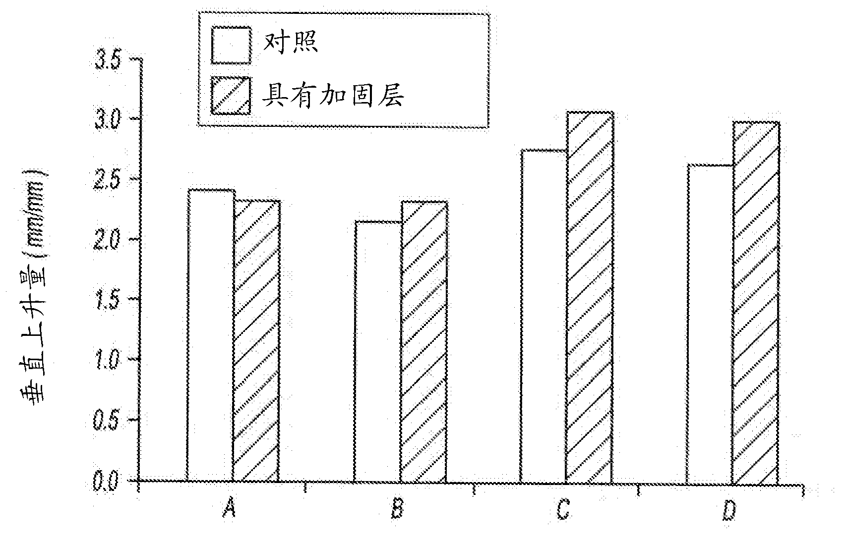
[0058] Table 3 provides a comparison of the properties of the two epoxy-based expandable structural foams in the neat state (eg, without a reinforcement layer) and in the form of a composite laminate using a polyester terephthalate film. All listed properties are for the material in the activated state.
[0059] Table 3 shows that the composite laminates of the invention have a higher relative vertical rise than the pure material. The reinforcement layer inhibits lateral (horizontal or in-plane) movement of the activated material such that the expansion is directed in a direction perpendicular to the plane or axis of the reinforcement layer.
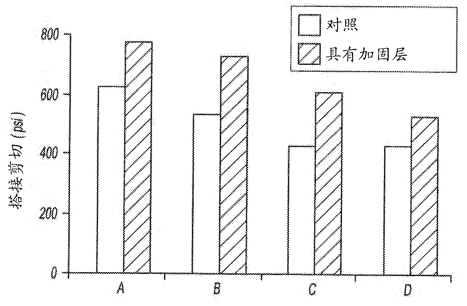
[0060] Lap shear strength was determined according to ASTM D1002 using a 3 mm bond wire and an EG-60 metal substrate. Table 3 shows that the composite structure has greater lap shear strength than the pure epoxy adhesive. The reinforcement layer effectively reduces the apparent bond line, resulting in greater lap shear strength.
[00...
Embodiment II
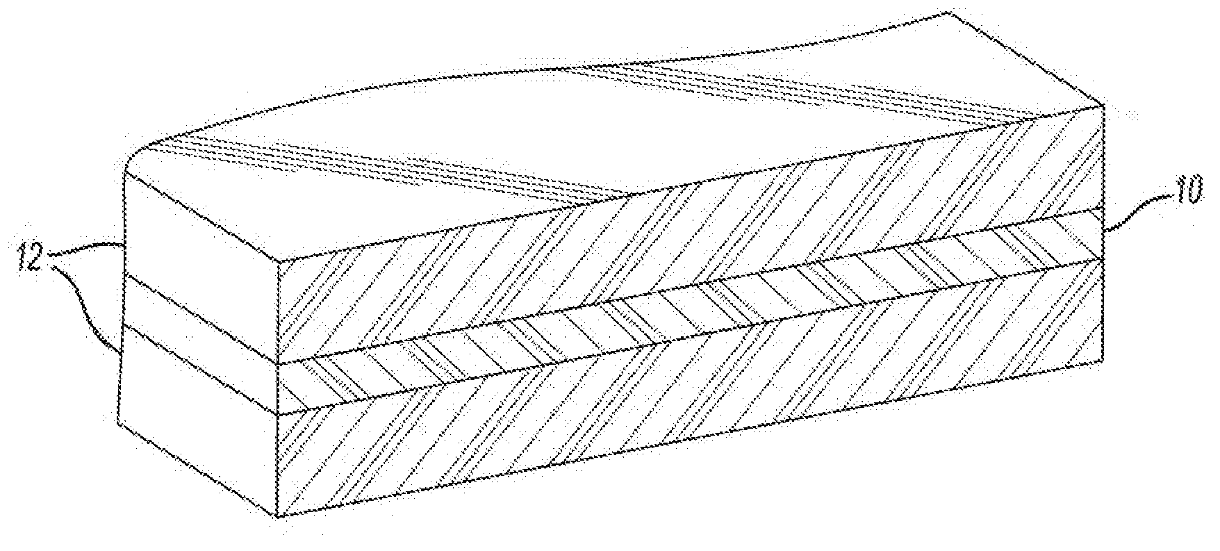
[0066] In this example, a composite structural laminate was prepared by pressing a 0.18 mm thick polyethylene terephthalate film between sheets of epoxy-based expandable structural foam. One example of this epoxy-based expandable structural foam is similar to the activatable material disclosed in US Patent No. 7,892,396, except that no core / shell polymer impact modifier is present. The sandwich structure was compressed in a heated press at 180°F for 2 to 3 minutes so that the membrane was substantially in the middle of the structure and the final thickness of the entire structure was about 3mm.
[0067] Table 4 provides a comparison of the performance of epoxy-based expandable structural foam in its neat state (without a reinforcement layer) and in the form of a composite laminate using a polyester terephthalate film. All listed properties are for the material in the activated state.
[0068] Table 4
[0069]
[0070] The experimental details are the same as given in Exam...
Embodiment III
[0072] Structural foams formed in accordance with the present invention also exhibit advantageous post-activation compression properties. In particular, the structural foams of the present invention were foamed into samples and then tested according to methods based on ASTM C39. While the method is described herein, it is understood that any parameters not specified are in accordance with ASTM C39.
[0073] Three different sample types were formed. The first sample was prepared by foaming pure (unreinforced) epoxy-based foam in cylinders or cylinder cups and then removing the excess foam that expanded from the cylinder or cylinder cups (e.g., Formed by cutting away the foam expanding from the cylinder or cylinder cup). The second sample was constructed by cutting discs from flat composite laminate samples and stacking them in cylinders or cylinder cups so that the plane of the PET reinforcement layer was perpendicular to the axis of the cylinder. The sample was then complet...
PUM
| Property | Measurement | Unit |
|---|---|---|
| surface tension | aaaaa | aaaaa |
| surface tension | aaaaa | aaaaa |
| surface tension | aaaaa | aaaaa |
Abstract
Description
Claims
Application Information