Ion beam distribution

A technology of ion beam and ion sub-beam, applied in ion beam tube, ion implantation plating, vacuum evaporation plating, etc., can solve the problem of low efficiency of sputtering target use

Active Publication Date: 2013-06-12
VEECO INSTR
View PDF4 Cites 9 Cited by
  • Summary
  • Abstract
  • Description
  • Claims
  • Application Information

AI Technical Summary

Problems solved by technology

Such non-uniform sputtering results in less efficient use of the sputtering target

Method used


Image

  • Ion beam distribution
  • Ion beam distribution
  • Ion beam distribution

Examples


Embodiment Construction

[0023] In the following description, for purposes of explanation, numerous specific details are set forth in order to provide a thorough understanding of the present invention. It will be apparent, however, to one skilled in the art that the present invention may be practiced without these specific details. For example, although various features may be attributed to particular embodiments, it should be understood that features described with respect to one embodiment may be combined with other embodiments as well. Similarly, however, no feature or features of any described embodiment should be considered essential to the invention, as other embodiments of the invention may omit these features.

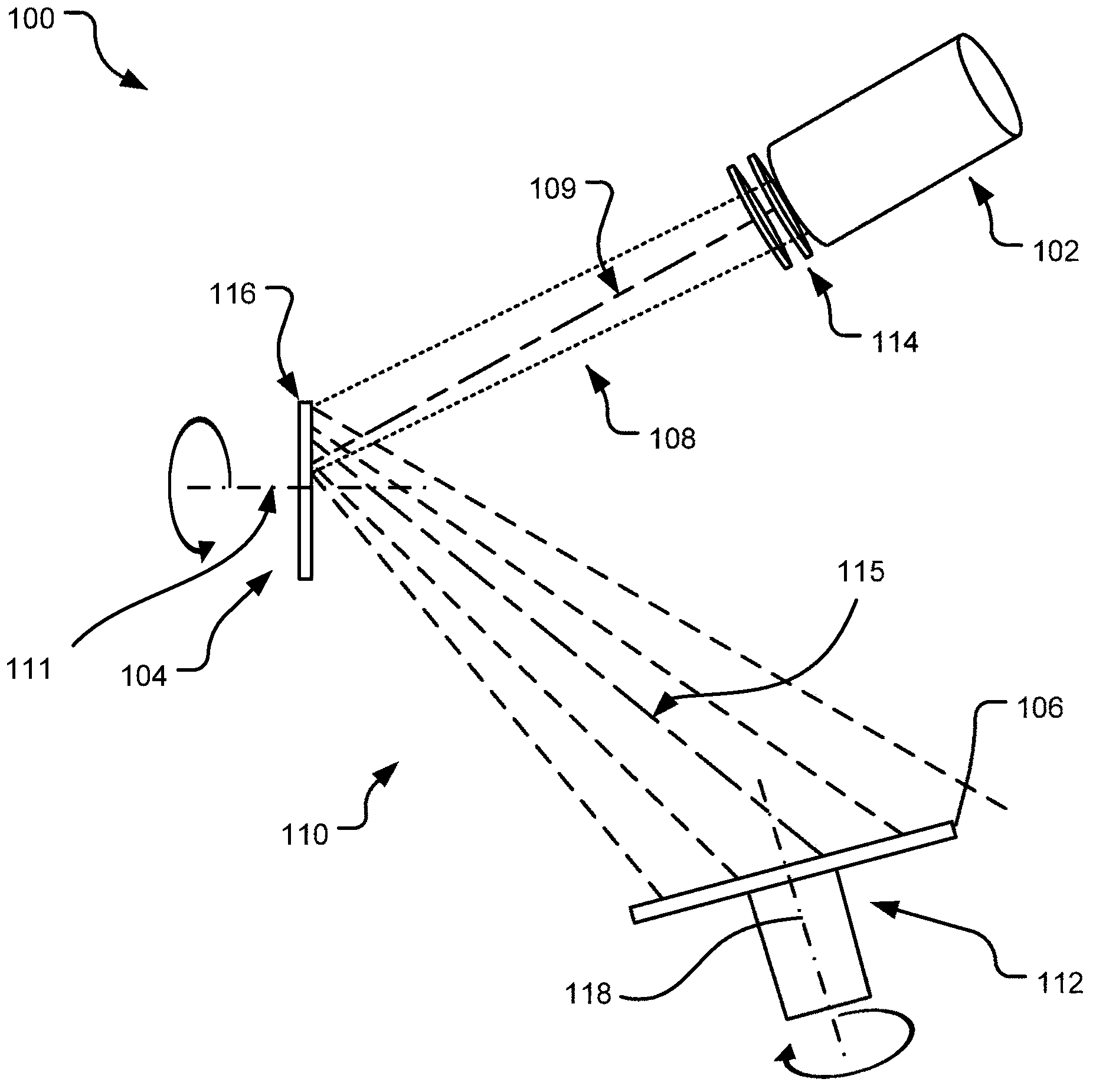
[0024] figure 1 An example block diagram of a beam steering ion beam system 100 is shown. Even though an embodiment of ion beam system 100 is implemented as an ion beam sputter deposition system, components of ion beam system 100 can be modified to implement ion beam etching systems,...


PUM


Abstract

An ion beam system (100) includes a grid assembly (300) having a substantially elliptical pattern of holes to steer an ion beam (108) comprising a plurality of beamlets to generate an ion beam (108), wherein the ion current density profile (700, 900, 1100, 1200) of a cross-section of the ion beam (108) is non-elliptical. The ion current density profile (700, 900, 1100, 1200) may have a single peak that is symmetric as to one of the two orthogonal axes of the cross-section of the ion beam (108). Alternatively, the single peak may be asymmetric as to the other of the two orthogonal axes of the cross-section of the ion beam (108). In another implementation, the ion current density profile may have two peaks on opposite sides of one of two orthogonal axes of the cross-section of the ion beam (108).; Directing the ion beam (108) on a rotating destination work-piece (104) generates a substantially uniform rotationally integrated average ion current density at each point equidistant from the center of the destination work-piece (104).

Description

[0001] Cross References to Related Applications [0002] This application claims the benefit of priority to US Patent Application Serial No. 12 / 898,281, filed October 5, 2010, and entitled "Ion Beam Distribution," which is hereby incorporated by reference herein in its entirety. This application further claims U.S. Patent Application Serial No. 12 / 898,424, filed October 5, 2010, entitled "Plume Steering" and U.S. Patent Application No. 12 / 898,424, filed October 5, 2010, entitled "Grid Providing Beamlet Steering" priority to patent application Ser. No. 12 / 898,351, which is specifically incorporated herein by reference in its entirety. technical field [0003] The present invention generally relates to ion beam systems and components thereof. Background technique [0004] When an ion beam system is used to sputter material away from a target to create a coating on a substrate, the ion beam system may be referred to as an ion beam sputter deposition system. Alternatively, the...

Claims


Application Information

Patent Timeline
Patent Type & Authority Applications(China)
IPC IPC(8): C23C14/46C23C14/34
CPCC23C14/46H01J27/024H01J37/08H01J2237/0656H01J2237/083H01J2237/3142H01J2237/3151H01J2237/31701
Inventor 龟山育也
Owner VEECO INSTR
Why Eureka
Try Eureka