

External-framework type bidirectional force feedback data glove
A technology of data glove and force feedback, applied in the field of data glove, can solve the problems of complex system, high price of force feedback data glove, difficult maintenance, etc.
- Summary
- Abstract
- Description
- Claims
- Application Information
AI Technical Summary
Problems solved by technology
Method used
Image

Examples
specific Embodiment approach 1
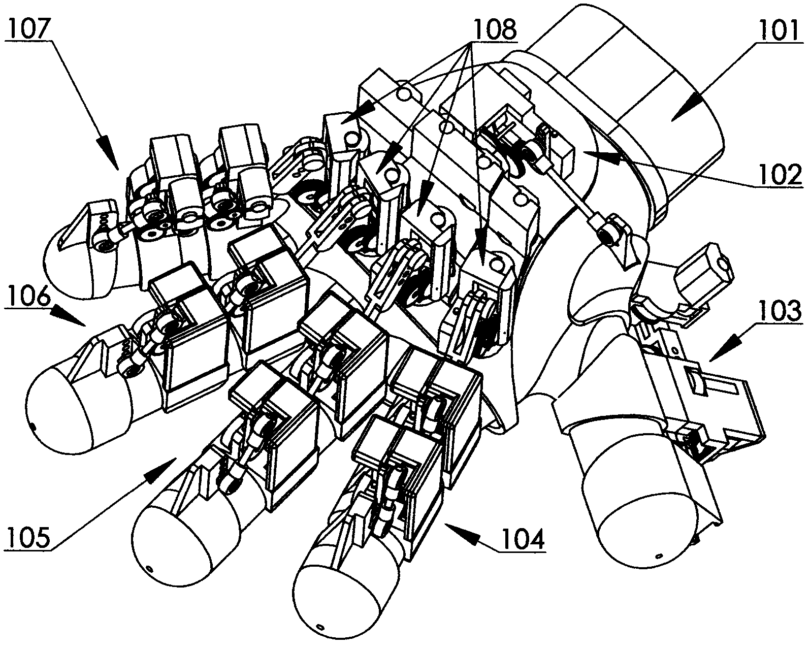
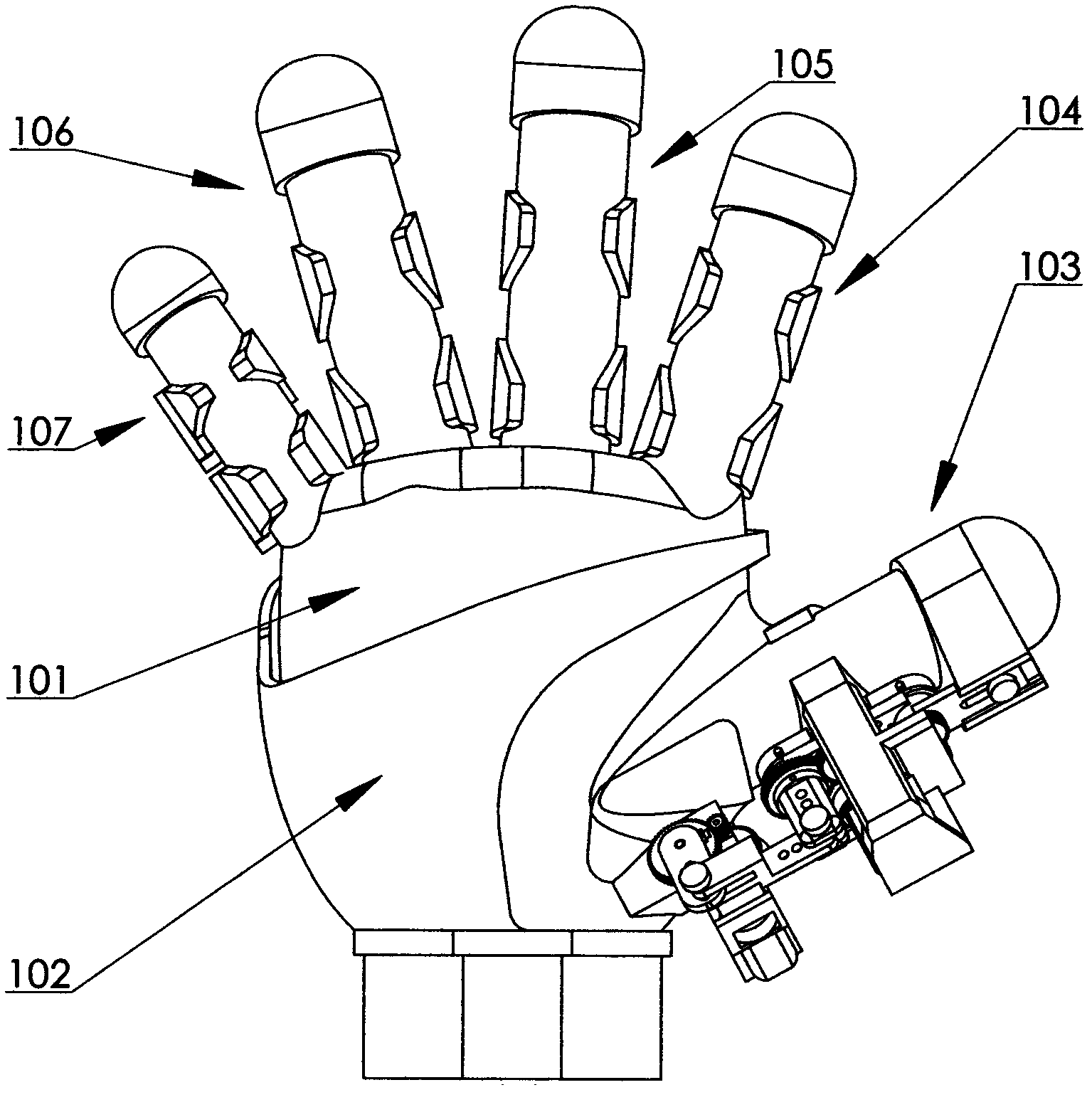
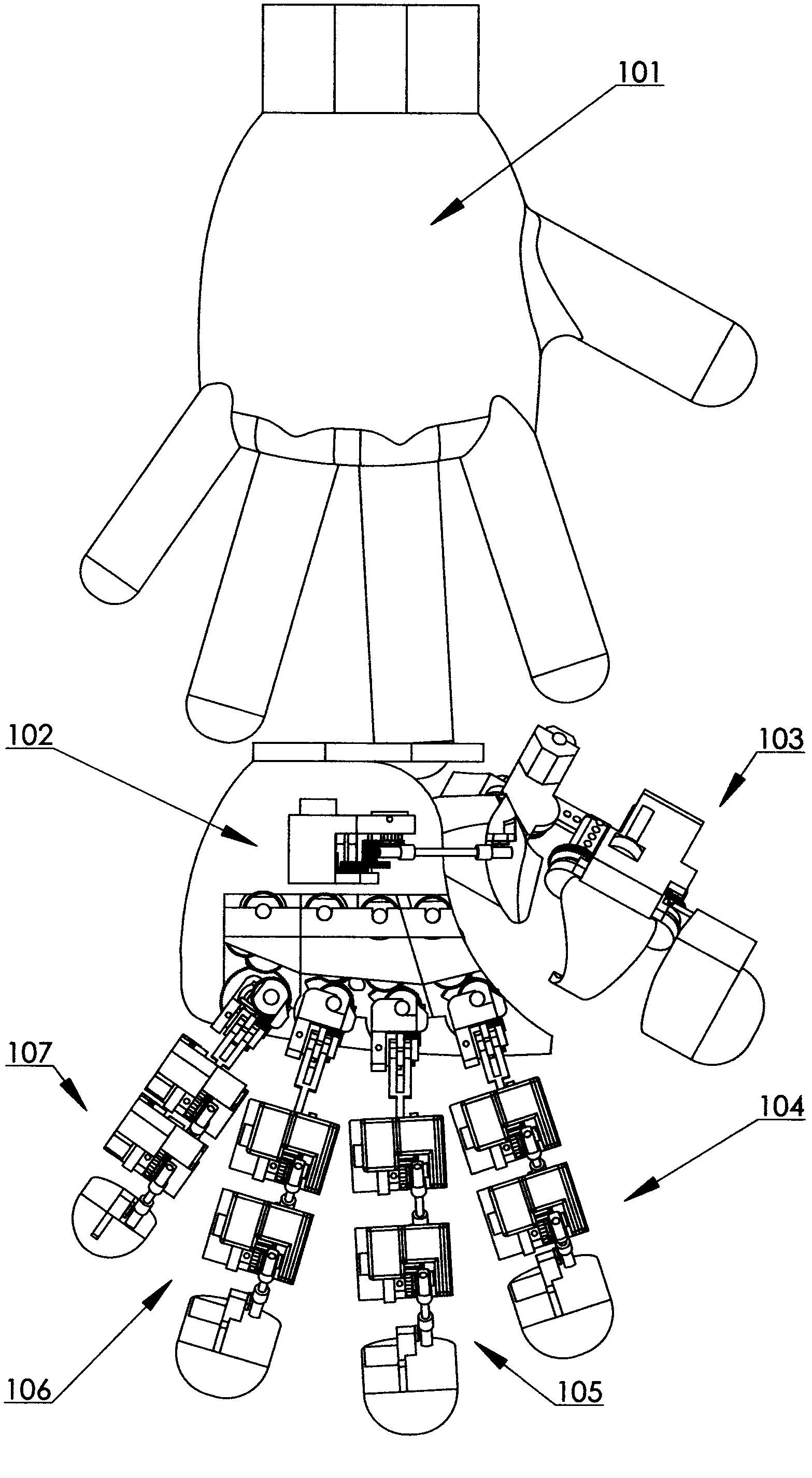
[0033] Specific implementation mode one: as figure 1 , figure 2 and image 3 As shown, the outer frame type two-way force feedback data glove includes a glove 101, a palm base 102, a thumb detection drive mechanism 103, an index finger detection drive mechanism 104, a middle finger detection drive mechanism 105, a ring finger detection drive mechanism 106, and a little finger detection drive mechanism. Mechanism 107 and metacarpophalangeal joint detection driving mechanism 108 . The outer frame type two-way force feedback data glove is suitable for most operators' hands of different sizes, so most of the components are preset with a plurality of installation holes arranged in a straight line, so that the operator can choose the appropriate one according to actual needs. Relevant components are installed in the position, so that the positions of each joint point of the data glove and each joint point of the operator's finger correspond to the best state. The glove 101 is ma...
specific Embodiment approach 2
[0034] Specific implementation mode two: as figure 1 , figure 2 , image 3 , Figure 4 , Figure 5 , Figure 6 and Figure 7 As shown, the thumb detection drive mechanism 103 includes a thumb metacarpophalangeal base 5, a thumb proximal knuckle base 4 and a thumb distal knuckle base 3 hinged sequentially with the palm base 102, and every two adjacent bases Angle sensors 18 and drive components 111 for detecting joint movement information are installed at the hinges of the seat to detect the position and motion state of each knuckle of the thumb in three-dimensional space, and realize the force feedback function under the action of the drive component 111.
[0035] like Figure 4 As shown, the driving part 111 includes a micro motor 40 and a clutch, and the clutch is composed of a clutch friction plate 41, a friction plate slide bar 42, a return tension spring 43, and a clutch cover 44. The friction plate slide bar 42 and the micro motor 40 The two clutch friction plate...
specific Embodiment approach 3
[0039] Specific implementation mode three: as figure 1 , Figure 8 and Figure 9 As shown, the metacarpophalangeal joint detection driving mechanism 108 includes a driving component 111 , a rocker arm 27 , a metacarpophalangeal joint base 29 , a connecting rod 38 , a gear case cover 50 and two angle sensors 18 . Metacarpophalangeal joint base 29 bottoms (embedded bearing 39) and the axle of an angle sensor 18 are fixedly connected by screw 36, and described metacarpophalangeal joint base 29 can rotate around the axis of bottom angle sensor (18), and described palm The lower outer edge of the knuckle base 29 is provided with a gear 59, the axis of the gear 59 coincides with the axis of the angle sensor 18 at the bottom of the metacarpophalangeal joint base 29, and the other angle sensor 18 is fixed on the metacarpophalangeal joint base by a screw 35. In the hole seat L of 29, the shaft of the angle sensor 18 and one end of the rocker arm 27 (embedded bearing 23) are fixedly c...
PUM
 Abstract
Description
Claims
Application Information