
Laser with low-voltage driven electro-optical crystal

A technology of electro-optic crystals and lasers, which is applied in the field of lasers, can solve the problems of limited optical aperture, impossibility, and single distance, and achieve the effects of improving stability and service life, reducing manufacturing difficulty and cost, and reducing internal loss

Inactive Publication Date: 2013-06-19
SHANGHAI INST OF OPTICS & FINE MECHANICS CHINESE ACAD OF SCI
View PDF3 Cites 11 Cited by
  • Summary
  • Abstract
  • Description
  • Claims
  • Application Information

AI Technical Summary

Problems solved by technology

However, the method of increasing the aspect ratio to reduce the half-wave voltage also has some insurmountable disadvantages: first, the larger the size of the crystal, the more difficult it is to grow, and the higher the cost; second, the single reduction of the distance between the electrodes, although lower half-wave voltage, but also limits the clear aperture
[0004] also, Figure 1 The laser coupling output rate shown is determined by the transmittance of the mirror (1-1), and its coupling output rate can only be a fixed value. To change the coupling output rate, it is necessary to replace the transflector with a different transmittance. mirror, it is impossible to adjust the coupling output ratio without replacing the laser resonator components

Method used


Image

  • Laser with low-voltage driven electro-optical crystal
  • Laser with low-voltage driven electro-optical crystal
  • Laser with low-voltage driven electro-optical crystal

Examples


Embodiment Construction

[0018] The present invention will be further described below in conjunction with the accompanying drawings and embodiments, but the protection scope of the present invention should not be limited thereby.

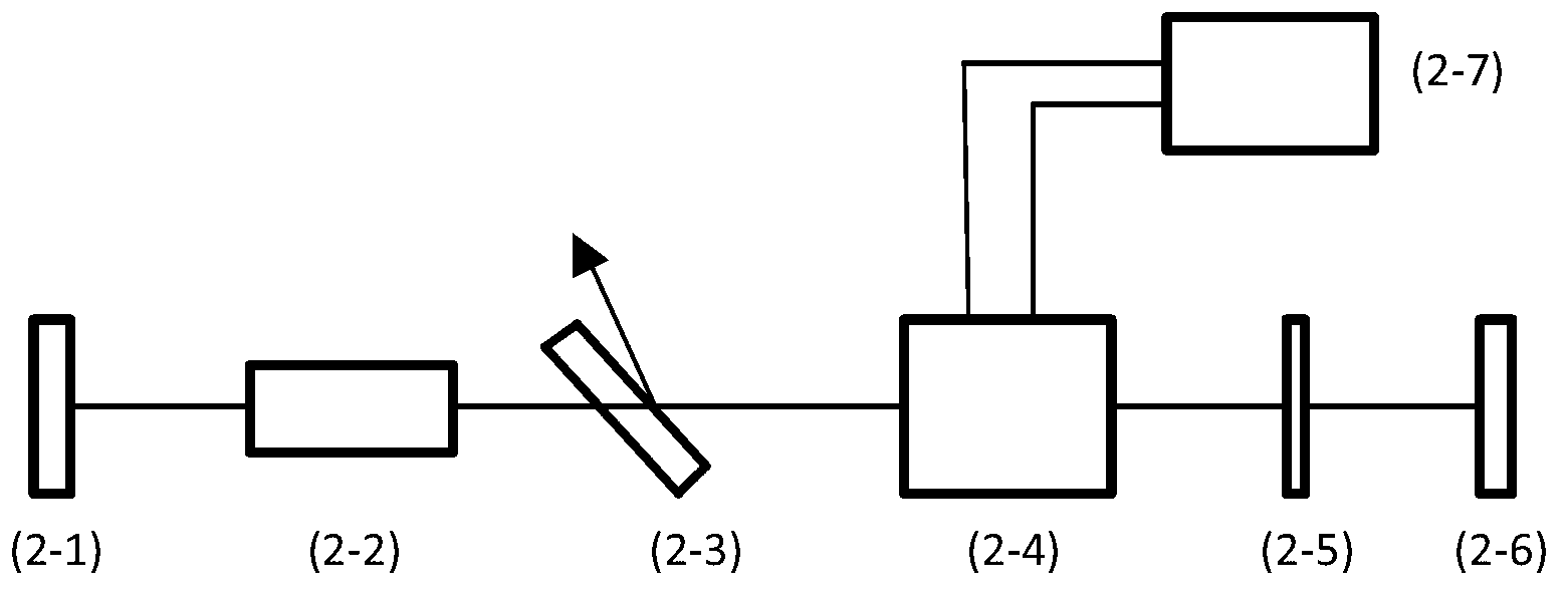
[0019] like figure 2 As shown, the low-voltage drive electro-optic crystal laser of the present invention comprises a first cavity mirror 2-1, a gain medium 2-2, a polarizer 2-3, an electro-optic crystal 2-4, and a wave plate 2 on the same optical axis in sequence. -5, the driving power supply 2-7 of the second cavity mirror 2-6 and the electro-optic crystal, the first cavity mirror 2-1, the gain medium 2-2, the polarizer 2-3, the electro-optic crystal 2-4, the wave Plate 2-5 and second cavity mirror 2-6 form a laser resonator, the polarizer 2-3 forms a certain angle with the optical axis, and the two ends of the electro-optic crystal 2-4 and the adjustable The driving power supply 2-7 is connected.

[0020] The laser light passes through the polarizer 2-3, passes throug...


PUM


Abstract

The invention discloses a laser with a low-voltage driven electro-optical crystal. The laser is characterized by sequentially comprising a first cavity mirror, a gain medium, a polarizing film, an electro-optical crystal, a wave plate, a second cavity mirror and a driving power supply for the electro-optical crystal, which have the same optical axis, wherein the polarizing film forms a certain angle with the optical axis; and the two ends of the electro-optical crystal are connected with the adjustable driving power supply. The laser has the advantages that driving voltage to be applied to the electro-optical crystal is low, so that the manufacture difficulty and cost of the driving power supply for the electro-optical crystal are greatly lowered, and the stability and reliability of the laser are improved; and the polarization coupling output rate of the laser can be controlled by changing the driving voltage of the electro-optical crystal.

Description

technical field [0001] The invention belongs to the technical field of lasers, and in particular relates to a laser for driving an electro-optic crystal with a low voltage. At the same time, the polarization coupling output rate of the laser can be controlled by changing the driving voltage of the electro-optic crystal. Background technique [0002] The electro-optic Q-switching switch uses the electro-optic effect of certain crystals to realize the adjustment of the Q value in the laser resonator. The electro-optic Q-switching switch has the advantages of short switching time, high efficiency, precise control of Q-switching time, narrow laser output pulse width, and high peak power. It is a Q-switching technology widely used at present. [0003] Traditional electro-optic Q-switched lasers generally use polarizers and electro-optic crystals to form a Q switch. According to the physical principle of electro-optic Q-switching, it is generally necessary to add a half-wave volt...

Claims


Application Information

Patent Timeline
IPC IPC(8): H01S3/115
Inventor 孟俊清杨海龙马秀华陈卫标
Owner SHANGHAI INST OF OPTICS & FINE MECHANICS CHINESE ACAD OF SCI
Learn More