Capacitor device

A capacitor and voltage technology, used in circuit devices, battery circuit devices, electric vehicles, etc., can solve problems such as power reduction, increase in internal resistance, and deterioration of capacitor components.

Active Publication Date: 2013-06-19
PANASONIC INTELLECTUAL PROPERTY MANAGEMENT CO LTD
View PDF5 Cites 11 Cited by
  • Summary
  • Abstract
  • Description
  • Claims
  • Application Information

AI Technical Summary

Problems solved by technology

[0006] In the conventional capacitor device 70, if the temperature is low, the capacitance of the capacitor element decreases and the internal resistance increases, so the power for storing electricity decreases and the storage performance deteriorates.
On the other hand, if it is at a high temperature, the power storage performance of the capacitor improves, but the capacitor element tends to deteriorate due to overcharging of the capacitor element

Method used


Image

  • Capacitor device
  • Capacitor device
  • Capacitor device

Examples


Embodiment approach 1

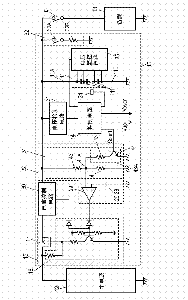
[0017] figure 1 It is a block circuit diagram of the capacitor device in Embodiment 1 of the present invention. The capacitor device 10 is an auxiliary power source for the main power source 12 , and includes a capacitor unit 11 connected between the main power source 12 and a load 13 to store electric power of the main power source 12 . When the power supply switch 33 is turned on by the control circuit 14 , the electric power accumulated in the capacitor unit 11 is output to the load 13 .

[0018] The capacitor unit 11 is composed of a plurality of capacitor elements 111 connected in series. The positive side terminal 11A of the capacitor part 11 is connected to the charging circuit 15, and the negative side terminal 11B is grounded.

[0019] Electric double layer capacitors (electric double layer capacitors), electrolytic capacitors, electrochemical capacitors, etc. can be used as the capacitor elements 111, and the number of capacitor elements 111 in the capacitor unit ...

Embodiment approach 2

[0063] Figure 4 It is a block circuit diagram of the capacitor device 510 in the second embodiment of the present invention. Figure 4 in, right with figure 1 The same parts of the capacitor device 10 in the first embodiment shown are given the same reference numerals. Capacitor device 510 in Embodiment 2 includes voltage control circuit 522 instead of voltage control circuit 22 in capacitor device 10 in Embodiment 1. FIG.

[0064] The voltage control circuit 522 is connected to the capacitor unit 11 and the charging circuit 15 , and includes a voltage dividing circuit 25 that divides the voltage of the capacitor unit 11 and outputs a divided voltage proportional to the voltage, a reference voltage circuit 27 , and a comparison circuit 29 .

[0065] The voltage dividing circuit 25 is composed of resistance elements 55 and 56 connected in series with each other at a connection point 55A. Resistive element 55 is grounded, and resistive element 56 is connected to positive te...

Embodiment approach 3

[0076] Figure 5 It is a block circuit diagram of the capacitor device 610 in Embodiment 3 of the present invention. Figure 5 in, right with figure 1 The same parts of the capacitor device 10 in the first embodiment shown are given the same reference numerals. Capacitor device 610 in Embodiment 3 includes voltage control circuit 622 including voltage dividing circuit 624 instead of voltage control circuit 22 including voltage dividing circuit 25 in capacitor device 10 in Embodiment 1.

[0077] The voltage dividing circuit 624 includes a plurality of variable resistance units 43A, 200 . The plurality of variable resistance units 43A and 200 are connected in parallel to the resistance element 41 .

[0078] The variable resistance unit 43A has a resistance element 43 and a semiconductor switching element 44 connected in series to each other, and the variable resistance unit 200 has a resistance element 243 and a semiconductor switching element 244 connected in series to each...


PUM


Abstract

A capacitor device includes a capacitor unit, a voltage-dividing circuit for outputting a divided voltage obtained by dividing a voltage of the capacitor unit, and a comparator circuit. The comparator circuit causes the charge circuit to operate such that the voltage of the capacitor unit reaches a full-charge voltage. The voltage-dividing circuit includes a semiconductor switching element, and outputs a divided voltage. A control circuit is operable to determine the full-charge voltage to be a high-temperature full-charge voltage by turning off the first semiconductor switching element when a temperature at the capacitor unit exceeds a reference temperature. The control circuit is operable to determine the full-charge voltage to be a low-temperature full-charge voltage that is higher than the high-temperature full-charge voltage by turning on the first semiconductor switching element when the detected temperature is not higher than the reference temperature.

Description

technical field [0001] The present invention relates to a capacitor device that controls charging of a capacitor unit. Background technique [0002] In recent years, vehicles such as electric vehicles and hybrid vehicles have been sold on the market in order to protect the environment and improve fuel efficiency. If such a vehicle is driven with a starter that consumes a large current intermittently during use, the voltage of the battery will temporarily drop. A capacitor device for a vehicle is used as an auxiliary power supply for supplying sufficient electric power to a load when the voltage of such a battery temporarily drops, or for supplying electric power to a braking system of a vehicle when the battery is abnormal. [0003] Figure 7 It is a block circuit diagram of a conventional capacitor device 70 . In the capacitor device 70 , a capacitor unit 71 is constituted by a plurality of capacitor elements that store the power of the battery of the main power supply, a...

Claims


Application Information

Patent Timeline
Patent Type & Authority Applications(China)
IPC IPC(8): H02M3/06H02M3/07
CPCH02J2310/48H02J7/00712H02J7/00308H02J7/007194Y02T10/70H02J7/00
Inventor 森田一树滨井秀晃小田岛义光
Owner PANASONIC INTELLECTUAL PROPERTY MANAGEMENT CO LTD
Why Eureka
Try Eureka