
Impedance matcher, semiconductor equipment and impedance matching method

A technology of impedance matching device and impedance matching network, which is applied in the field of microelectronics, can solve the problem that the impedance sensor cannot accurately measure the input impedance related signal of the second impedance matching device, cannot accurately measure the input impedance of the impedance matching device, and cannot accurately measure the input impedance of the impedance matching device. The problem of measuring input impedance-related signals and other problems, to achieve the effect of simple dual-frequency signal interference, simple structure, and long service life

Inactive Publication Date: 2013-06-19
BEIJING NAURA MICROELECTRONICS EQUIP CO LTD
View PDF4 Cites 15 Cited by
  • Summary
  • Abstract
  • Description
  • Claims
  • Application Information

AI Technical Summary

Problems solved by technology

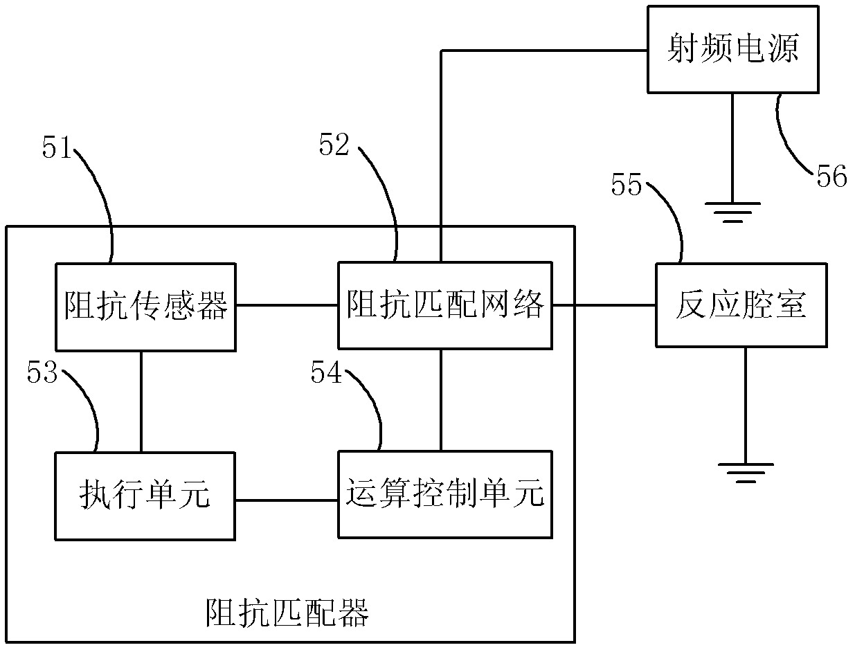
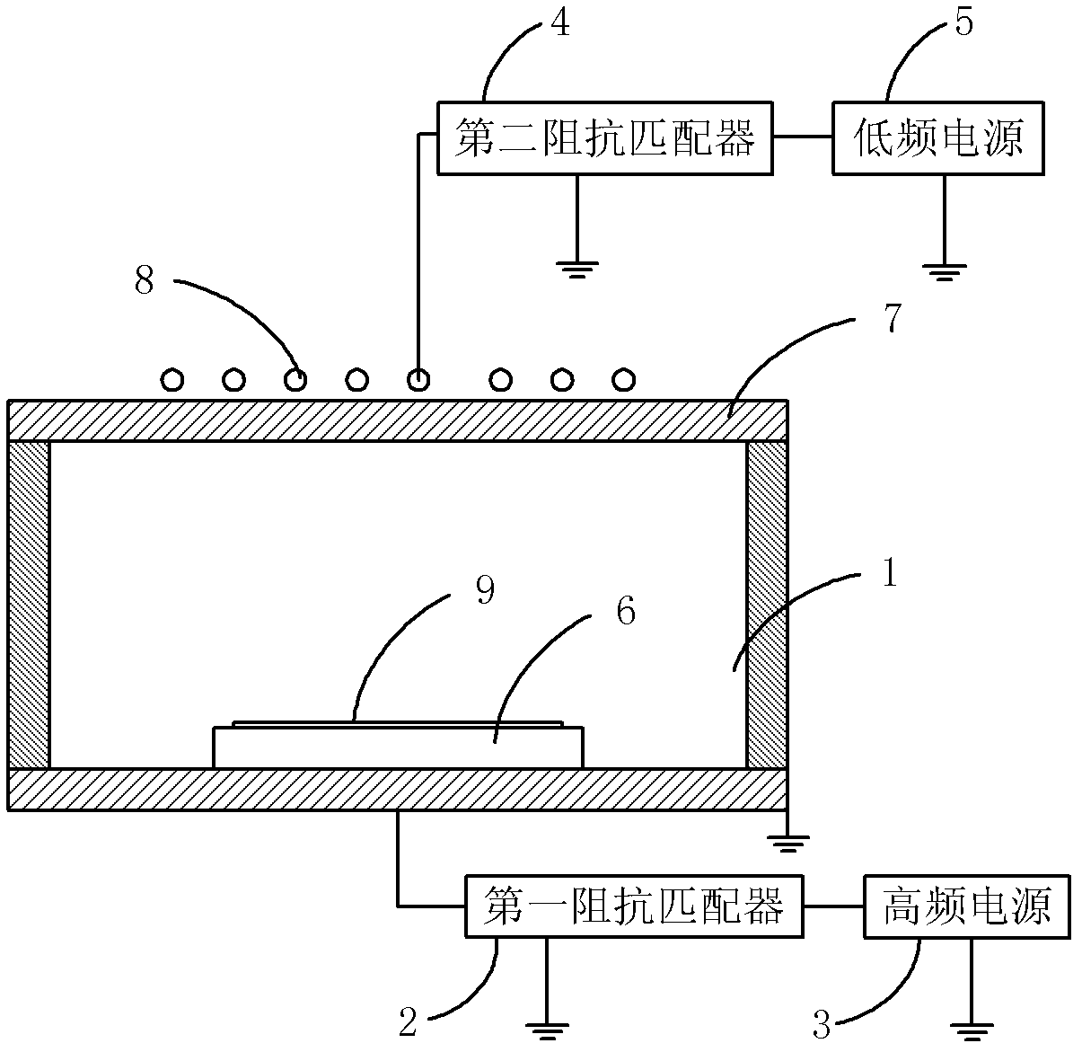
[0005] However, the plasma equipment adopts the structure of dual radio frequency power supply, and the two radio frequency power supplies will produce a dual frequency interference effect, which makes it impossible for the impedance sensor to accurately measure the input impedance of the impedance matching device. For example, high frequency interference signals will interfere The impedance sensor in the second impedance matching device makes the impedance sensor unable to accurately measure the input impedance related signal of the second impedance matching device; the low-frequency interference signal will interfere with the impedance sensor in the first impedance matching device, so that the impedance sensor cannot Accurately measure the input impedance related signal of the first impedance matcher, which reduces the measurement accuracy of the impedance sensor, so that the impedance matcher cannot achieve impedance matching

Method used


Image

  • Impedance matcher, semiconductor equipment and impedance matching method
  • Impedance matcher, semiconductor equipment and impedance matching method
  • Impedance matcher, semiconductor equipment and impedance matching method

Examples


Embodiment Construction

[0055] In order for those skilled in the art to better understand the technical solution of the present invention, the impedance matching device, semiconductor device and impedance matching method provided by the present invention will be described in detail below with reference to the accompanying drawings.

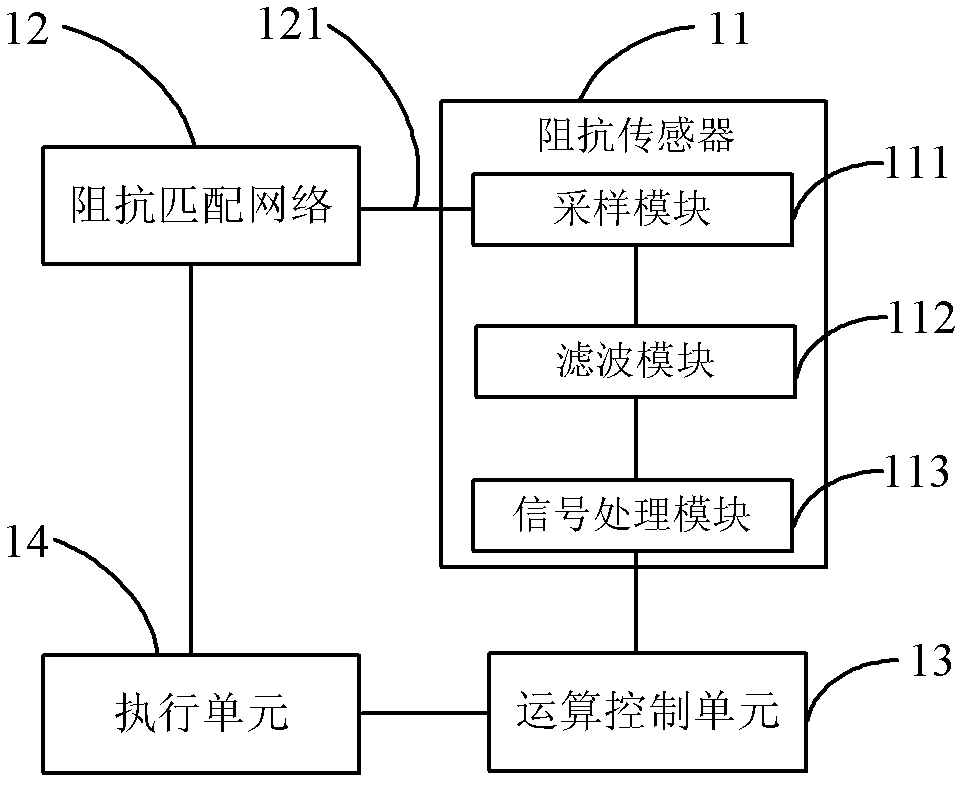
[0056] image 3 A schematic structural diagram of an impedance matching device provided in Embodiment 1 of the present invention, as shown in image 3 As shown, the impedance matching device includes an impedance sensor 11, an impedance matching network 12 connected to the radio frequency power supply and the impedance sensor 11, an operation control unit 13 connected to the impedance sensor 11, and an execution unit connected to the operation control unit 13 and the impedance matching network 12. The unit 14 , the impedance sensor 11 includes: a sampling module 111 connected to the impedance matching network 12 , a filtering module 112 connected to the sampling module 1...


PUM


Abstract

The invention discloses an impedance matcher, semiconductor equipment and an impedance matching method. The impedance matcher comprises an impedance sensor, an impedance matching network, a computing control unit and an execution unit. The impedance sensor comprises a sampling module, a filter module and a signal processing module. The sampling module is used for detecting an input end of the impedance matching network and obtains impedance detecting signals. The filter module is used for filtering out interference signals with specific frequency in the impedance detecting signals. The signal processing module is used for carrying out computing processing on the impedance detecting signals after filter processing to generate input impedance relevant signals of the impedance matching network. The computing control unit is used for carrying out computing processing on the input impedance relevant signals to generate impedance adjusting data. The execution unit is used for adjusting the impedance matching network according to the impedance adjusting data so that input impedance of the adjusted impedance matching network and output impedance of a radio-frequency power supply are matched in a conjugate mode. The impedance matcher can accurately achieve impedance matching.

Description

technical field [0001] The invention relates to the technical field of microelectronics, in particular to an impedance matching device, a semiconductor device and an impedance matching method. Background technique [0002] Plasma is widely used in the production process of semiconductor devices. In plasma equipment, an RF power supply provides RF signal energy to a reaction chamber to generate plasma. Plasma contains a large number of active particles such as electrons, ions, excited atoms, molecules, and free radicals. These active particles interact with the wafer placed in the reaction chamber and exposed to the plasma environment, causing various occurrences on the wafer surface. Physical and chemical reactions, so that the surface properties of the wafer change, and the etching or other processes of the wafer are completed. [0003] In order to match the output impedance of the RF power supply with the impedance of the reaction chamber, an impedance matcher (Impedance...

Claims


Application Information

Patent Timeline
Patent Type & Authority Applications(China)
IPC IPC(8): H03H7/38
Inventor 成晓阳
Owner BEIJING NAURA MICROELECTRONICS EQUIP CO LTD
Learn More