Hydraulic pressure automodulation pulling-type clutch release bearing assembly

A release bearing, self-aligning technology, applied in clutches, fluid-driven clutches, non-mechanical-driven clutches, etc., can solve the problems of easy wear at the contact point, difficulty in shifting gears, and high impact noise, and achieve no impact noise and separation. Smooth, simple structure effect

Active Publication Date: 2013-06-26
WUXI MINLIAN AUTOMOBILE PARTS CO LTD
View PDF5 Cites 5 Cited by
  • Summary
  • Abstract
  • Description
  • Claims
  • Application Information

AI Technical Summary

Problems solved by technology

This form of separation and combination has the following defects: in the process of frequent separation and combination, the separation sleeve slides reciprocatingly on the shaft sleeve of the gearbox I for a long time, and it is easy to wear each other; The support surface of the shift fork is in two-point contact, and the impact noise is large, especially when the release bearing pulls the diaphragm spring release finger to realize the separation of the clutch. After the uneven wear of the shift fork bearing surface of the two lugs on the sleeve, the operation feeling is not good, and the gear shifting is difficult

Method used


Image

  • Hydraulic pressure automodulation pulling-type clutch release bearing assembly
  • Hydraulic pressure automodulation pulling-type clutch release bearing assembly
  • Hydraulic pressure automodulation pulling-type clutch release bearing assembly

Examples


Embodiment Construction

[0023] Below the present invention will be further described in conjunction with the embodiment in the accompanying drawing:

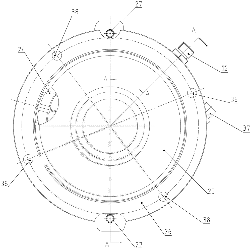
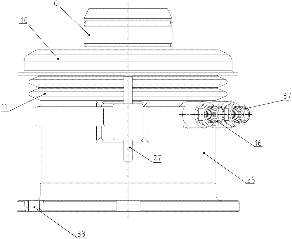
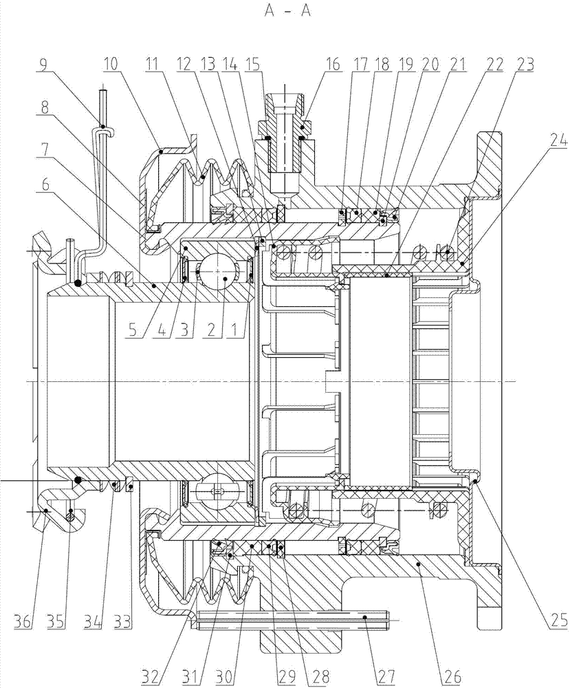
[0024] like Figure 1~3 As shown, the present invention mainly includes the piston 7 and the cylinder body 26, and the hydraulic cylinder oil cavity is formed between the inner circle surface of the cylinder body 26 and the outer circle surface of the piston 7. On the inner circle surface of the left end of the cylinder body 26, the cylinder body dustproof sealing ring 32, the cylinder body snap ring 31, the cylinder body plastic spacer 30, the cylinder body hydraulic sealing ring 29 and the cylinder body ring 28 are successively installed from left to right, and the cylinder body The outer circle of the body dust-proof sealing ring 32 is in interference fit with the inner surface of the cylinder body 26, and the inner lip of the cylinder body dust-proof sealing ring 32 is tightly pressed against the outer circle surface of the piston 7, which can effe...


PUM


Abstract

The invention relates to a hydraulic pressure automodulation pulling-type clutch release bearing assembly, in particular to a pulling-type clutch release bearing assembly used for medium heavy-duty cars, and belongs to the technical field of an automobile clutch. The pulling-type clutch release bearing assembly comprises a piston and a cylinder body. A cylinder body dustproof sealing ring, a cylinder body snap ring, a cylinder body plastic space ring, a cylinder body hydraulic pressure sealing ring and a cylinder body ring are sequentially installed on an inner circle surface of the left end of the cylinder body from left to right. A piston dustproof sealing ring, a piston snap ring, a piston plastic space ring, a piston hydraulic pressure sealing ring and a piston ring are sequentially placed on an outer circle surface of the right end of the piston from right to left. The pulling-type clutch release bearing assembly is simple, compact and reasonable in structure, abrasion-free, impact noise-free, stable in separating, good in operation and convenient to shift, and speed can be changed conveniently.

Description

technical field [0001] The invention relates to a hydraulic self-aligning pull-type clutch release bearing assembly, in particular to a pull-type clutch release bearing assembly for medium and heavy vehicles, and belongs to the technical field of automobile clutches. Background technique [0002] The existing automobile pull-type clutch release bearing in the automobile clutch separation system realizes clutch separation and combination in the form that the driver steps on the clutch pedal, and the release fork pulls the release sleeve (release bearing seat) to drive the release bearing on the shaft tube of the gearbox I. Sliding on the sleeve in the axial direction, the release bearing pulls the diaphragm spring separation finger to separate the driven plate of the clutch, cut off the power input from the engine to the gearbox, and realize the separation function of the clutch; release the clutch pedal, and the diaphragm spring separation finger pulls to separate The bearin...

Claims


Application Information

Patent Timeline
Patent Type & Authority Applications(China)
IPC IPC(8): F16D25/12F16C33/78F16C33/58
Inventor 邵济民孙惠勇张伟张磊
Owner WUXI MINLIAN AUTOMOBILE PARTS CO LTD
Why Eureka
Try Eureka