
Method and system for pilot frequency bi-phase coincidence detection based on coincidence pulse counting

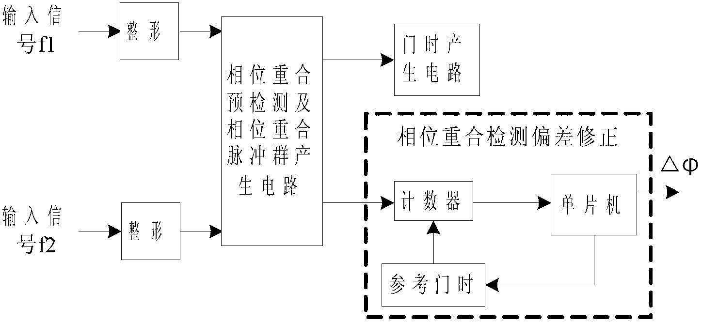
A dual-phase coincidence and phase coincidence technology, which is applied in the conversion of frequency to pulse sequence, the phase angle between voltage and current, and frequency measurement devices, can solve the impact of phase coincidence detection output pulses and the reduction of the accuracy of the measurement comparison system , phase coincidence detection phase deviation and other issues, to achieve the effect of improving accuracy and measurement resolution, eliminating influence, easy integration and productization

Inactive Publication Date: 2013-06-26
XIDIAN UNIV
View PDF2 Cites 19 Cited by
  • Summary
  • Abstract
  • Description
  • Claims
  • Application Information

AI Technical Summary

Problems solved by technology

[0006] There is a common shortcoming in the existing methods, that is, there is a problem of response resolution in the electronic circuit, which is generally on the order of nanoseconds or hundreds of picoseconds. If there is phase noise or trigger error on the signal or two-way measurement comparison, it will have a relatively large impact on the output pulse of the phase coincidence detection, so that there will be a phase deviation in the final phase coincidence detection, which will greatly reduce the accuracy of the entire measurement comparison system
None of the existing phase coincidence detection methods can fundamentally eliminate the phase coincidence detection error caused by phase noise and trigger error, let alone correct the phase coincidence detection error

Method used


Image

  • Method and system for pilot frequency bi-phase coincidence detection based on coincidence pulse counting
  • Method and system for pilot frequency bi-phase coincidence detection based on coincidence pulse counting

Examples


Embodiment Construction

[0029] In order to make the object, technical solution and advantages of the present invention clearer, the present invention will be further described in detail below in conjunction with the accompanying drawings and embodiments. It should be understood that the specific embodiments described here are only used to explain the present invention, not to limit the present invention.

[0030] figure 1 The schematic diagram of the phase coincidence pre-detection and phase coincidence pulse group generation circuit for different frequency signals. As shown in the figure, this circuit has two square wave input comparison signals: f1 and f2. Each signal must pass through the following modules in sequence from input to output:

[0031] The adjustable delay module is connected with the NAND gate, and is used to perform adjustable delay processing on the input square wave signal;

[0032] The NOT gate is connected with the adjustable delay module and the AND gate, and is used for inv...


PUM


Abstract

The invention discloses a system and a method for pilot frequency bi-phase coincidence detection based on coincidence pulse counting. The system comprises a pilot frequency signal phase coincidence pre-detection and phase coincidence pulse group generation circuit, a bi-phase coincidence detection phase deviation correction circuit and a gate delay generation circuit. By utilizing a group phase coincidence principle among pilot frequency signals and by combining the phase coincidence pre-detection and phase coincidence pulse group generation circuit and coincidence pulse counting, gate information needed by measurement comparison is given, and a phase coincidence detection deviation value can be resolved by the aid of a coincidence pulse count value so as to correct a final measurement result. By the method, influences of phase noise and trigger error on phase coincidence detection are eliminated, and the realized phase difference coincidence detection can reach measurement resolution superior to picosecond. Besides, the method is capable of improving precision of phase coincidence detection and measurement resolution, and a circuit is simple in structure and easy for integration and productization.

Description

technical field [0001] The invention belongs to the technical field of time-frequency measurement and control, and in particular relates to an ultra-high-resolution different-frequency dual-phase coincidence detection system and method based on coincidence pulse counting. Background technique [0002] The measurement and comparison of time-frequency quantities play an important role in the field of time-frequency measurement and control technology. With the continuous improvement of the accuracy and stability of the frequency base standard, higher requirements are put forward for the corresponding measurement comparison technology. At present, the frequency standard system of high performance index generally reaches 10 -14 / τ frequency stability and 1×10 -16 The above measurement accuracy cannot be achieved without the measurement technology that matches the improvement of frequency standard technology. These high-resolution measurements and comparisons cannot be realized....

Claims


Application Information

Patent Timeline
Patent Type & Authority Applications(China)
IPC IPC(8): G01R25/00G01R23/10
Inventor 董绍锋胡为杜保强周渭屈八一詹劲松秦红波史琳李辰
Owner XIDIAN UNIV
Learn More