Partial discharge detection test platform of medium-voltage switch cabinet

A partial discharge detection and test platform technology, which is applied in the direction of testing dielectric strength, etc., can solve the problems of unsatisfactory detection effect of photomultiplier tube, weak signal, and no consideration of humidity, etc., so as to achieve easy movement and operation, good safety, and improved The effect of experimental efficiency

Active Publication Date: 2013-06-26
ELECTRIC POWER RES INST OF GUANGDONG POWER GRID
View PDF7 Cites 19 Cited by
  • Summary
  • Abstract
  • Description
  • Claims
  • Application Information

AI Technical Summary

Problems solved by technology

The Chinese invention patent "A Partial Discharge Detection Device for Switchgear" (application publication number CN 102749557A) discloses a method for detecting partial discharge signals using ultra-high frequency sensors, acoustic emission sensors, high-frequency current sensors and TEV sensors, but only It involves detection methods without specific fault models and test parameters; the Chinese patent "A 10kV Switchgear Partial Discharge Detection System" (authorized announcement number CN 202471902) discloses a method of using transient-to-earth voltage (TEV) technology to monitor the A system for detecting partial discharge signals based on pin-plate discharge, insulation gap and floating potential fault models. This system is also equipped with auxiliary detection equipment such as photoelectric detection and acoustic wave detection. However, the initial signal of partial discharge is generally very weak and there will be no bright light. The detection effect of photomultiplier tube may not be ideal, on the other hand, this system does not consider the influence of humidity

Method used


Image

  • Partial discharge detection test platform of medium-voltage switch cabinet
  • Partial discharge detection test platform of medium-voltage switch cabinet
  • Partial discharge detection test platform of medium-voltage switch cabinet

Examples


Embodiment Construction

[0035] The partial discharge detection test platform of the medium-voltage switchgear provided by the present invention will be further explained below in conjunction with the accompanying drawings.

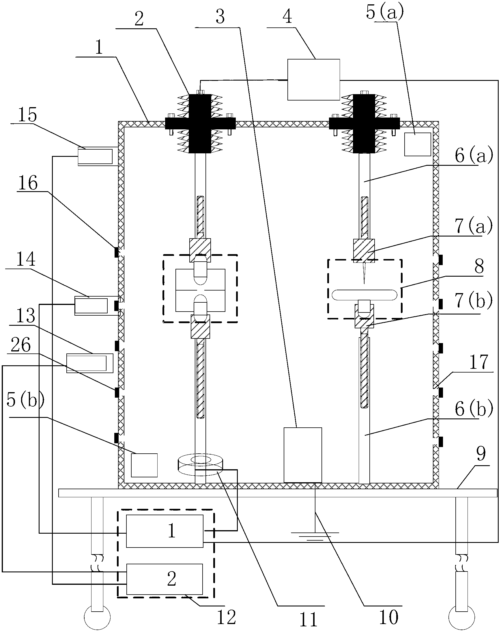
[0036] Such as figure 2 As shown, the medium-voltage switchgear partial discharge detection test platform of the present invention includes a support platform 9, a metal cabinet body 1, a signal detection unit, a fault model 8 and a power frequency high voltage source.

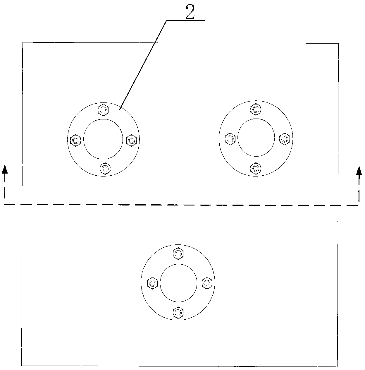
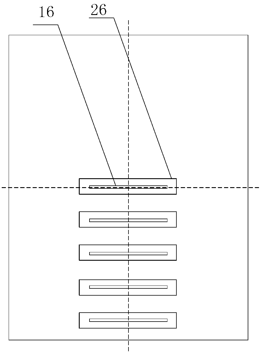
[0037] The outer dimension of the metal cabinet 1 is 800*800*1000mm 3 , wall thickness 1.5mm, see image 3 and Figure 4 , the left and right sides of the metal cabinet body 1 are respectively provided with 5 equidistant square holes. There is a magnetic shutter 26 .

[0038] There is a humidifier 3 inside the metal cabinet, and thermo-hygrometers 5(a) and 5(b) are arranged on the inner wall of the metal cabinet body 1 up and down for monitoring the temperature and humidity in the cabinet.

[0039] There ar...


PUM


Abstract

A partial discharge detection test platform of a medium-voltage switch cabinet comprises a metal cabinet, a fault model, three conducting rods and a signal detecting unit. The conducting rods are symmetrically vertically arranged in the metal cabinet, each conducting rod is formed by an upper conducting rod body and a lower conducting rod body, the upper ends of the upper conducting rod bodies penetrate through the top of the metal cabinet to be connected with wiring columns while the lower ends of the same are connected with the fault model the upper ends of the lower conducting rod bodies are connected with the fault model while the lower ends of the same are connected with the metal cabinet. The signal detecting unit comprises a ultrasonic wave sensor, a ultrahigh frequency sensor, a TEV (transient earth voltage) sensor, Rogowski coils, high-voltage probes, and a power-frequency high-voltage source, wherein the ultrasonic wave sensor and the ultrahigh frequency sensor are arranged near a square hole of the metal cabinet and respectively connected with a first digital oscilloscope and a second digital oscilloscope, the TEV sensor is adhered on the outer surface of the metal cabinet and connected with the second digital oscilloscope, the Rogowski coils are coiled on the lower conducting rod bodies, the high-voltage probes are arranged on high-voltage inlet wires of the insulator wiring columns, the Rogowski coils and the high-voltage probes are all connected with the first digital oscilloscope, and the power-frequency high-voltage source is connected with the wiring columns. The partial discharge detection test platform of the medium-voltage switch cabinet is capable of simulating partial discharging in the real switch cabinet, convenient to move and operate, considerable in insulation distance, and good in safety.

Description

technical field [0001] The invention relates to a test platform, in particular to a test platform for partial discharge detection in a medium-voltage switch cabinet. Background technique [0002] The medium voltage switchgear is the most direct equipment to supply power to users. The power grid requires the switchgear to work stably for a long time, but on the one hand, the switchgear inevitably leaves technological defects during manufacturing, on the other hand, it is affected by factors such as electromagnetic heating, environmental humidity, and dust, especially in the southeastern coastal areas of my country. High humidity under certain weather conditions will seriously weaken the insulation strength. According to a statistical survey from 1989 to 1997, among the faults of switchgear, insulation faults and current-carrying faults accounted for about 40% to 50%. In the early stage of the development of insulation current-carrying faults, it generally manifests as local ...

Claims


Application Information

Patent Timeline
Patent Type & Authority Applications(China)
IPC IPC(8): G01R31/12
Inventor 王流火卢启付吕鸿王宇宁文军王立军王海靖吴琛贾申利
Owner ELECTRIC POWER RES INST OF GUANGDONG POWER GRID
Why Eureka
Try Eureka